Diagnosing Electrical Short in KIM-1
SHARE |
|
 Diagnosing Electrical Short in KIM-1
 |
by Bill Degnan - 08/23/2014 11:12 |
|
The unit worked according to the seller, but has a short causing immediate overheat/power supply hiss when 5V applied so I have to test with the power off. I will have to compare and contrast with the other KIM-1 I have (does not work but does not have a short). Sent inquiry via vintage-computer.com to see if anyone has any ideas.
See thread here: http://www.vintage-compu...-Diagnosing-KIM-1-short Reply |
|
 Rockwell KIM-1 Rev D
 |
by Bill Degnan - 08/23/2014 23:23 |
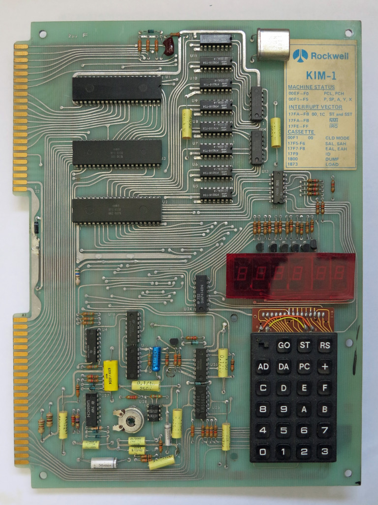
 Rockwell, MOS or CBM Kim-1? It's a rev D that should be Commodore, but the brand is obscured by a metal plate. There is no date stamp above the serial number that I have seen in another rev D. Perhaps this is one of the KIM-1's from the transition between MOS and Commodore. Or maybe a Rockwell or other OEM Kim-1. But did Rockwell sell rev D's? The date codes of the chips are mostly early 1977, some late 1976 and the layout is the same as other KIMs that I have seen. Note the serial number is PA2079. This same pattern was used by Commodore in later revisions. PA most likely indicates Norristown, Pennsylvania, USA. Click image for larger view.
Here is another rev D, but it does not look much like mine: http://gc.org/rc2011sc/ I think the evidence says it's a Rockwell KIM-1 with the sticker/card removed as pictured here: http://retro.hansotten.n...5/IMG_9755-768x1024.jpg So far I have found nothing definitive about the various revisions of KIM-1, and there are few actual good photos of KIMs on the web, at least compared with other computers of this era. So, I will do some research in my library and post what I find here. ... Useful info: http://www.6502.org/trainers/buildkim/kim.htm Reply |
|
|
Troubleshooting KIM-1 |
by Bill Degnan - 08/25/2014 23:06 |
|
Working through system..
1. Removed shorted zener diode between application and expansion edge connectors. This solved problem with power supply (immediately hiss upon power) 2. Replaced tant cap near 6502, was probably ok but it's a tant so it's a good idea to replace them when they're old just in case 3. replaced resistor near zener diode 4. getting pulse at pin 39 of CPU At this point, applying power using a new 5V regulated supply returns exactly 5.00 volts in numerous places consistently, so now it's time to work through schematic. 1. pin 40 of 6502 goes low when RS (reset pressed) 2. It looks like a consistent wave on pin 39 and 3 on the 6502, but I'd like to see what a "good" one looks like. Mine is a slightly dirty looking wave but I don't expect a perfect sin wave either. 3. U16 pins 13, 12, 11 and 10 have a clock. 6502 A0/A1 have pulse 4. U4 (74145) D = nothing, A,B,C pulse after reset 5. U4 K0 = high, K5=high, K6=high, K7=high 6. transistor Q1 legs snapped off (both collector and emitter) need to replace (pnp transistor b>20 , vce>12 - 2n5371). tested base of Q2-Q6 by connecting base to ground with a 1Kohm resistor in the middle - all lit up. 7. tested 7406 in u17 using TTL tester - reports "passed". Reply |
|
|
KIM's alive! |
by Bill Degnan - 08/26/2014 13:32 |
|
Silly silly me. I did not realize I needed to ground application connector pin K. Doing so and the computer sprang to life. The U4's K0, K5, K6, K7 all went low (compare with note above) with application connector K grounded. The ROMs are in RAM and everything is peachy. More testing needed but it looks good so far.
Ironically, I bought this KIM because I gave up on my original CBM KIM-1 rev G ever working again. oh well. Next, I will attach to a teletype and play around with both of them, see what they can do. I may have enough parts to make a RAM extension. NOTE to anyone reading this: U4 has a set of K pins (see schematic), not to be confused with the K pins of the application and expansion connectors. Reply |
|
|
Rockwell KIM-1 Rev D Photos |
by Bill Degnan - 08/27/2014 09:54 |
 Photo of Rockwell KIM-1 Rev D from early 1977 with bad Q1 transistor which prevents activation of the left-most LED. Click image for larger view.
 Transistor Q1 has broken off, note the bare posts where Transistor Q1 should be. No biggie part on order. Rockwell put a plastic cover over the 6 individual LED displays, which is a good way to ID this as a MOS-manufactured OEM KIM-1. These boards may not have been sold bare to hobbyists. Instead they may have been sold by Rockwell to be embedded the heart of custom systems for industrial/business purposes, robots, projects, etc.. Click image for larger view.
More Photos Here is a photo of the application connector power wiring from my Commodore KIM-1, so you can see what it looks like. Same exact thing on both KIM-1's. I soldered up a few pins that I could remove without having to disconnect the adapter or use alligator clips. Reply |
|
Resources:

Popular Topics and FAQs
Past Issues:
Before we switched over to a blog format, past page archives here:
Vintage Computer Festival East 3.0 June 2006
Commodore B Series Prototypes July 2006
VOLSCAN - The first desktop computer with a GUI? Oct 2006
ROBOTS! - Will Robots Take Over? Nov 2006
Magnavox Mystery - a Computer, or? Jan 2007
The 1973 Williams Paddle Ball Arcade Computer Game Feb 2007
The Sperry UNIVAC 1219 Military Computer May 2007
VCF East 2007 - PET 30th Anniversary June/July 2007
The Electronic Brain August 2007
Community Memory and The People's Computer Company October 2007
Charles Babbage's Calculating Machine December 2007
Vintage Computing - A 1983 Perspective February 2008
Laptops and Portables May 2008
From Giant Brains to Hobby Computers - 1957 to 1977 August 2008
Historic Computer Magazines November 2008
World's Smallest Electronic Brain - Simon (1950) December 2008 - Feb 2009
Free Program Listings Spring 2009
Computer Music Summer 2009
Popular Electronics Jan/Feb 1975 - Altair 8800 Fall 2009
Early Microcomputer Mass Storage Summer 2010
Gavilan SC

This image was selected at random from the archive. Click image for more photos and files from this set.