Digital (DEC) PDP 11/05 NC Assembly
SHARE |
|
 Digital (DEC) PDP 11/05 NC Assembly
 |
by Bill Degnan - 06/09/2009 07:37 |
Ted Nelson speaks quite highly of the Digital PDP 11 series in his book Computer Lib / Dream Machines.
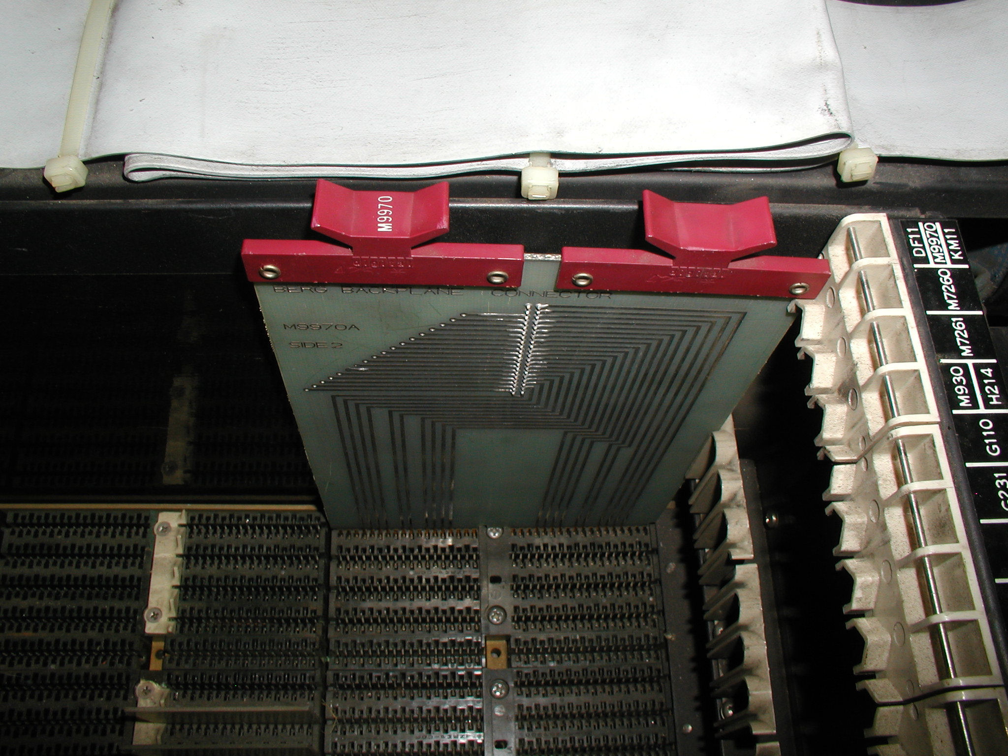
 Picture of the PDP 11/05 NC card cage and M9970(in the wrong slot). Click image for hi res version.
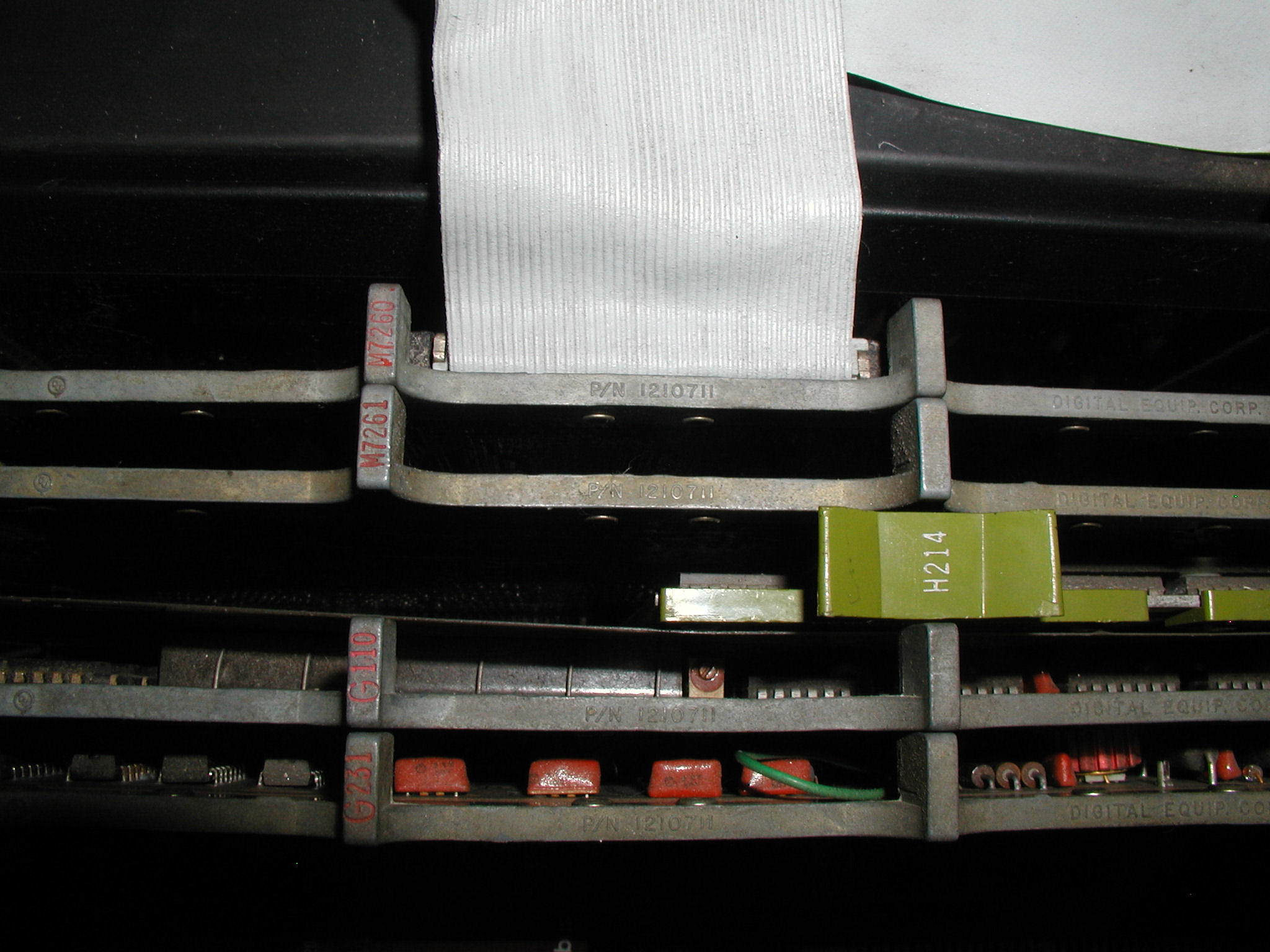
The only thing that prevented DEC from launching the PC revolution three years earlier was price, in my opinion. All of the other ingredients were there for a fine PC. The PDP 11/05 was the OEM version of the PDP 11/10, so you find all kinds of variations of this system sometimes paired with the DEC GT40 Graphic Display Terminal. Complete set of Pictures Some notes... 1) Cleaned (enough for now).. got all of the styrofoam peanuts, dust. 2) Started with an basically empty chassis other than a M9970 UNIBUS to connect expansion backplane to the main backplane and a few grant continuity cards, which must be present when no other card is in the row. Also present an M7856 serial card. 2.5) Added M9970 Berg backplane connector in the first slot up front. 3) Installed the logic boards M7260, M7261. 4) Added 8K core memory. H214 8K Core Memory with some sort of Companion card M930 in the remaining slots of the row, and between them a thin piece of metal shielding. 5) Next add G231 (memory driver) and G109C (control and data loops) into the first set of slots marked G231 and G110. So here is where we are so far.. 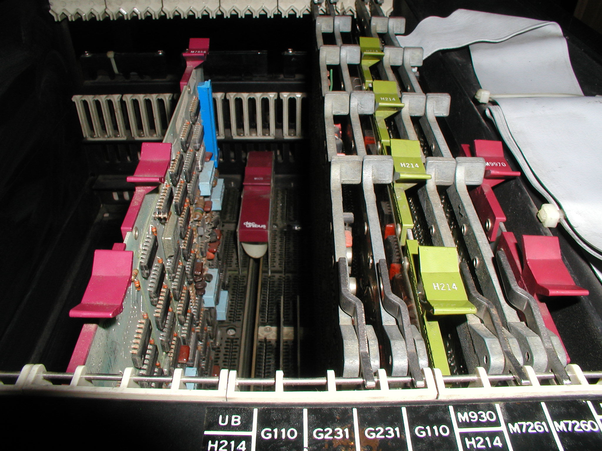 The card card guide labels for a DEC PDP 11/05 NC Computer (which differs from the 11/05 S). Click image for view of all cards installed into unit.
More to come.... Reply |
|
 Interfacting a VT-52 terminal
 |
by Bill Degnan - 08/29/2010 09:08 |
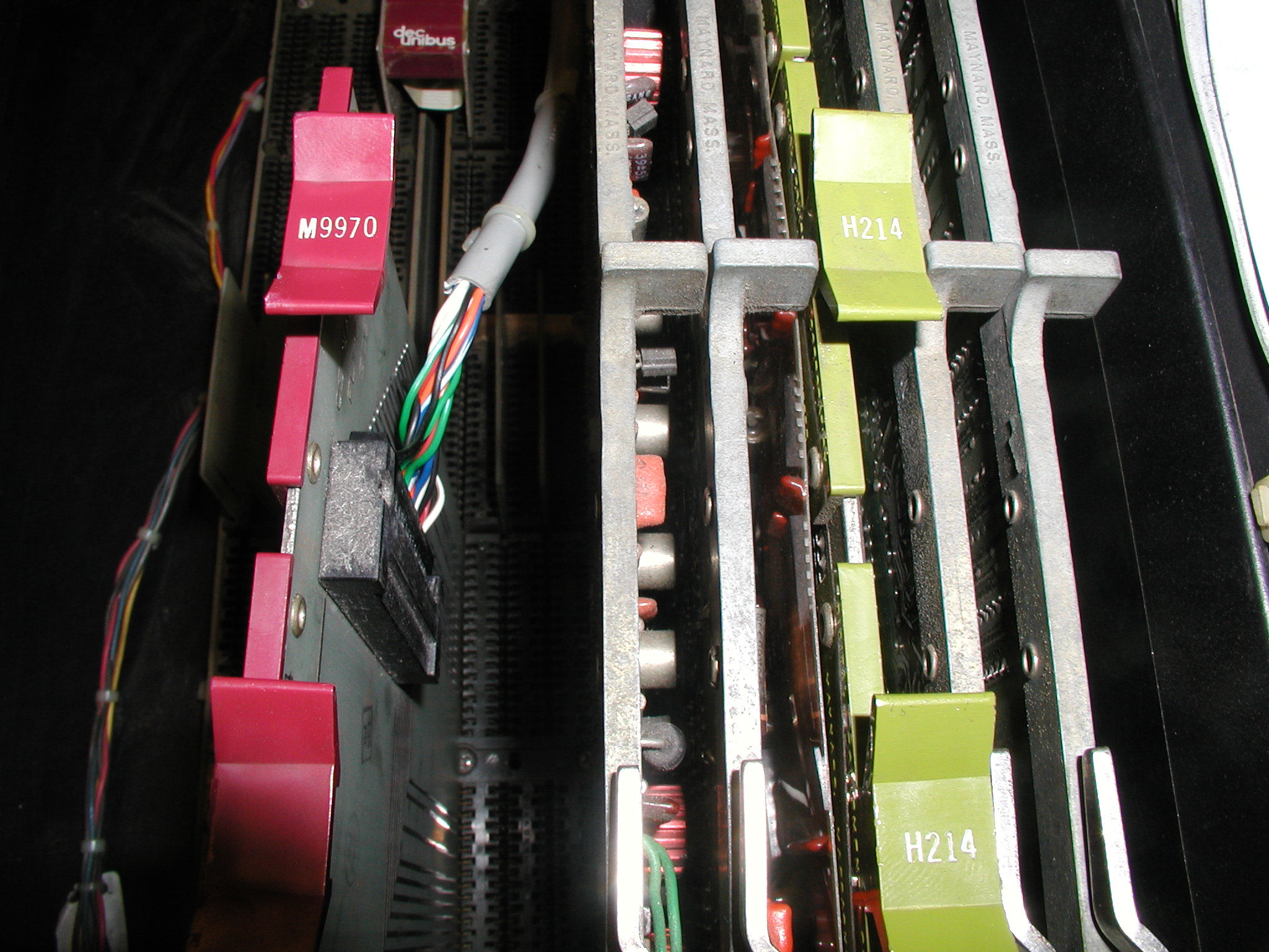 This photo is a closeup of the M9970 console card after it had been moved into a more convenient location from the front of the bus. A continuity card was inserted in it's place. Click image for larger view. [NOTE: Since this post I moved the M9970 to the center of the first card slot per the card placement diagram on the chassis.]
The system and interface cable are set for a 110baud/20mAmp teletype if you connect directly with the console, but The goal is to use the M7856 serial/clock card for faster RS232 communications using a serial terminal like a VT-52. I do not believe the VT-52 that I have has a current loop option. The processor itself is OK, if you load and run the following program from 177700: 000240 000777 the computer will set the lowest address bit to 0-1-0-1 continuously. If you "run / halt" and observe the last light on the right (0); half of the time there should be a light. If it's always lit, or always not, there is a problem with the CPU at least. Check power supply. NEXT This page provides tips that relate to this project, the 11/10 is the same thing as the 11/05: http://www.shiresoft.com/pdp-11/11-10/index.html Here setup info http://www.pdp-11.nl/per...terface/dl11w-info.html The user manual http://www.bitsavers.org...-DL11W-OP-001_May77.pdf Google 177560, including in google books, you might find a page like this one http://www.fpns.net/willy/pdp11/pdptrbsh.htm http://ftp.wayne.edu/ibi...1/hardware/dl11-w.info2 http://www.conservatique.com/pdp/pdp-1105 Reply |
|
|
Attempts to Interface with 11/05 |
by Bill Degnan - 09/03/2010 10:47 |
|
Moved the M9970 to the proper location in the bus, it needs to be in the middle slots.
Matt and I were not able to send any data (or so it seems) through either the M9970 console interface or a M7856 I/O clock card. No evidence of data (no voltage) passing through the cable to indicate the attempt. Not 100% sure we have a working program either. We're not sure what ports to use with the M7856 while a M9970 is also installed, does a conflict exist? Reply |
|
 Installing DL11-W
 |
by William Pechter - 09/09/2010 10:54 |
|
The 7856 can be set up many ways.
If the console card's in place you need to pick a different address that doesn't conflict. The common address and vector was 776510 address 300. The clock is normally disabled if there's a second 60HZ line clock interrupt. I don't have the pdp11/05/10 docs handy... The jumper info is here: http://www.bitsavers.org...-DL11W-OP-001_May77.pdf The enable disable for the line clock is in switchpack 5 (see pdf pg 2-01) Appendix b-4 has the vector addressing. Drop me mail or give me a call anytime. I'll try to find my PDP11 setup docs. Bill Pechter Reply |
|
|
Installing Memory |
by William Pechter - 09/09/2010 10:56 |
|
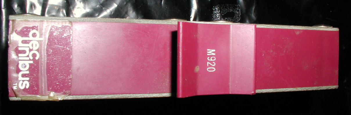
The M930's not really a companion card.
It's a bus terminator. Been since '85 or so since I touched one of these (at Princeton Plasma Physics)... It had a bad DL11 card IIRC. Reply |
|
|
Using M9970 Console with 11/05 |
by Bill Degnan - 02/13/2011 20:34 |
|
Project Update
I decided to run more system checks before doing more work with the M7856. I have the "PDP-11/05, 11/10 10 1/2 inch Mounting Box and Power System" Supplement 1. This has info on the interface cable and how to set up the PDP 11/05 with a serial terminal or teletype. Using a teletype as I/O is ideal for a proper restoration, eh? I have a teletype, so why not try to interface that with the 9970 console first? If that works, I will have more confidence that I can hook up the M7856. 1. Tested memory more extensively - OK 2. Removed M7856 card for now, replaced with another Grant Cont. card. 3. Ran "Line Time Clock Interrupt Test" from 001000, returned the expected value of 000104. That means the clock is running. Turned off system, reloaded program and got same result - RAM held in core memory. 4. I have the cable that connects the M9970 to a teletype. 5. NEXT determine the wiring from the asr 33 teletype call control unit assembly interface cable Reply |
|
|
ASR 33 Teletype testing |
by Bill Degnan - 03/01/2011 21:07 |
|
I completed the wiring, but I did not get the reaction I was expecting.
I have to make sure my teletype works properly. I am using my SWTPC 6800 to compare and contrast with the 11/05, and how they two interact with the teletype. I made the wiring connection as described in my thread above, but the system does not go into ready mode when the computer powers on. I assume that the teletype should go into ready mode, I could be wrong about that. When I turn on the teletype without it being attached to the SWTPC 6800 computer, it clicks and clacks and the ribbon advances. When I power on the computer, the teletype immediately stops clicking and clacking and waits for input. That's what I mean by "ready mode". I can then type at the teletype as if it were a computer terminal. (The swtpc has a monitor ROM) I am starting to think that maybe I need to run the 11/05 bootstrap loader to get the same effect? Or does the teletype go into ready mode if it detects a 20ma current loop? more to come Reply |
|
|
Teletype connection complete |
by Bill Degnan - 03/20/2011 17:29 |
|
The SWTPc and PDP 11/05 are not the same, the negative lines need to be separated.
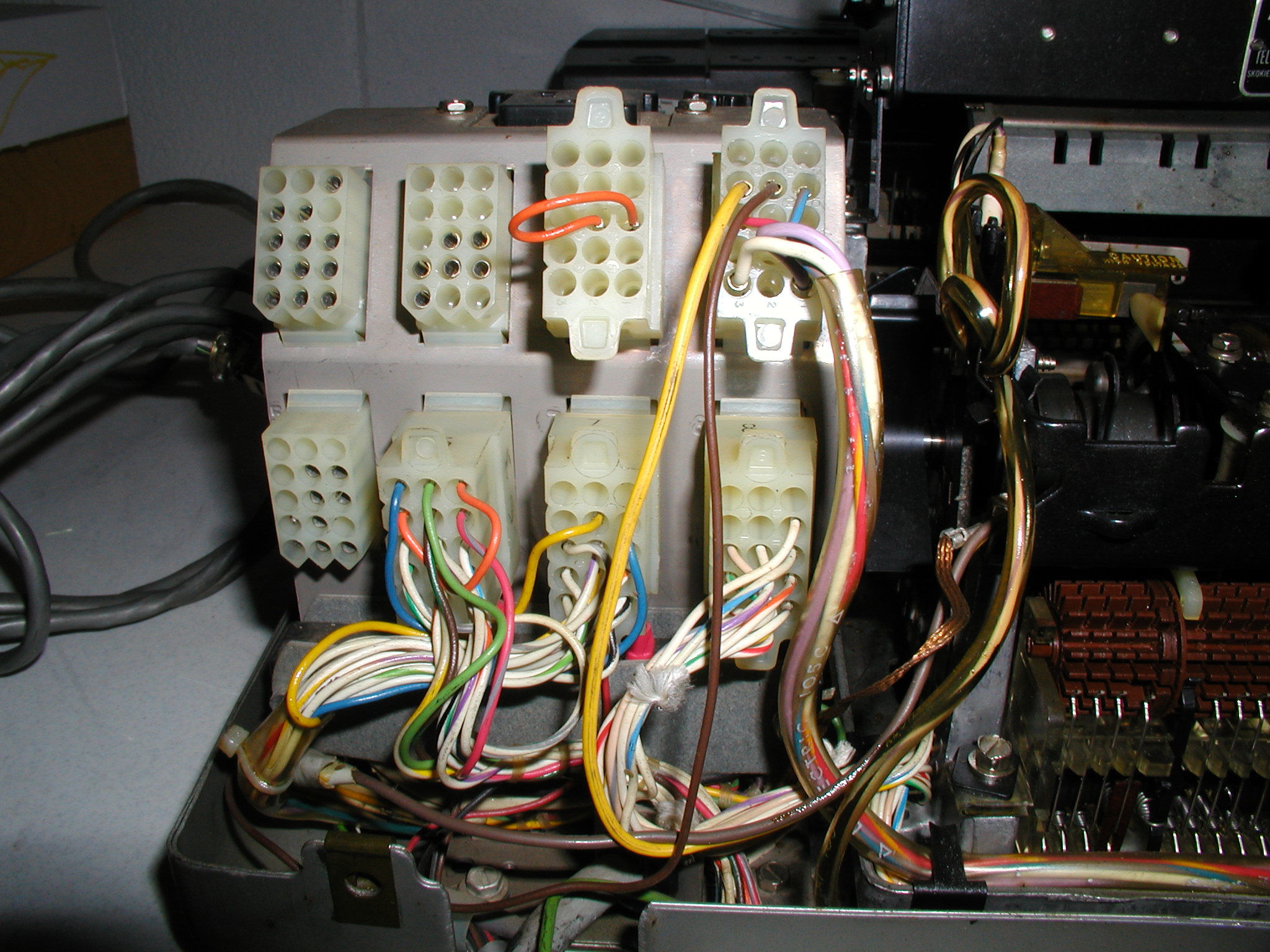
Here is a PDF of the cabling coming from the pdp 11/05, and the description of what wires are input and what wires are output. On the PDP 11/05 M9970 I can ID the TTY signals coming from the Berg connector. 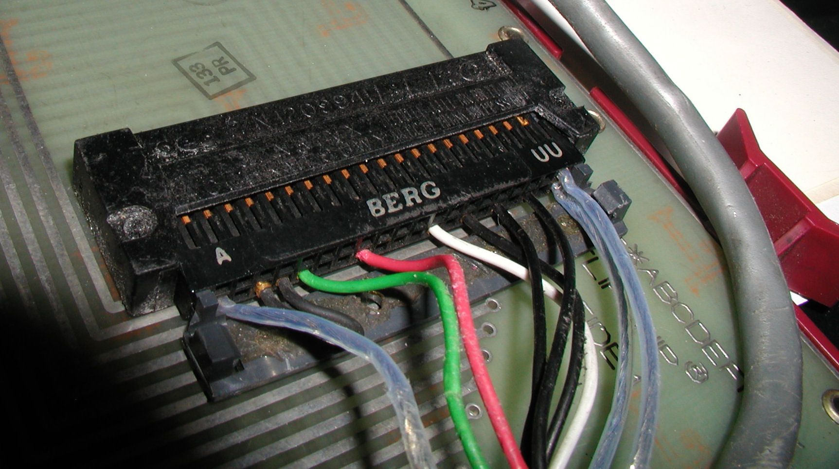 Photo of the wires coming from the Berg connector of the M9970 console card. Click for larger image.
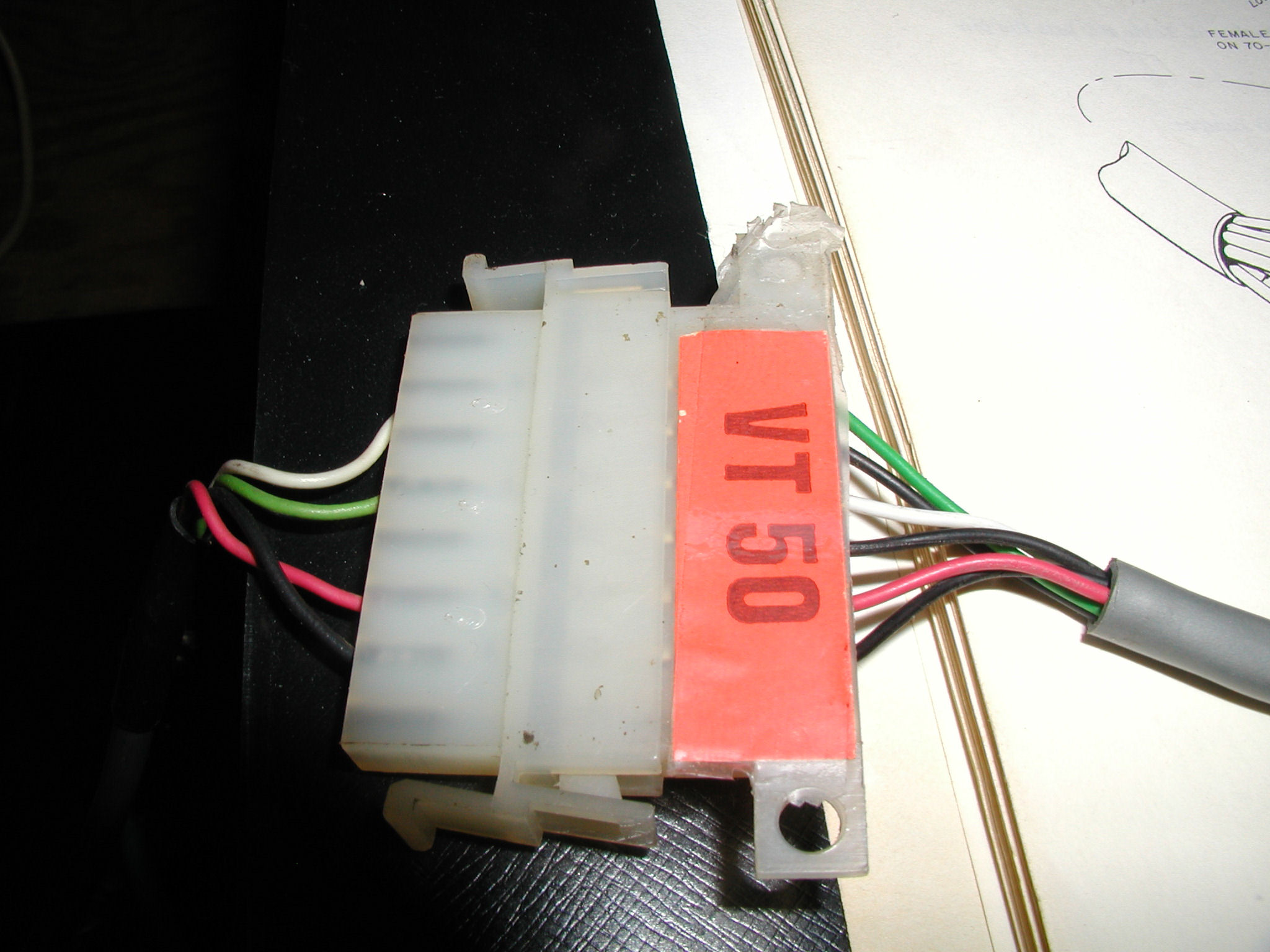 Photo of the wires coming from the mate and lock connector end of the M9770 I/O cable. Output (left): White = Receive+, Green = Transmit Data +. The black = - Transmit data and red = - receive data. Click for larger image. Note that on the other end, the white and green are reversed.
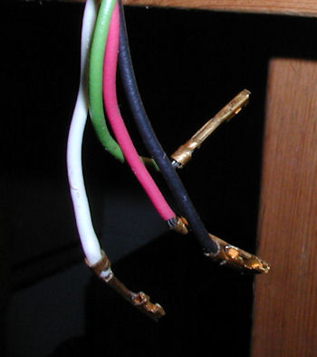 Lastly, these are the 4 wires that need to be inserted into the teletype. The white and green are reversed (white is + received, green is + transmitted)
Reference Photos: teletype pics The correct connections are Transmitted data return (-) attaches to terminal strip screw 6 or "number 2 connector" #7 Received data return (-) attaches to terminal strip screw 3 or num 2 connector #5 Transmitted data send (+): Terminal Strip 7, #2 connector 8 received data send (+): Term strip 4, #2 connector #6. Connector #2 is one of the eight connectors behind the call control unit (near the three fuses). #2 is second from the left. Pin hole one is located at bottom right, see array below: 15-14-13 12-11-10 09-08-07 06-05-04 03-02-01 You can bypass the connector by attaching the 4 wires directly to the terminal strip. The terminal strip is located behind/below the connectors. If you're making a cable with a special connector to match your particular computer card EITHER the terminal strip or #2 connector can be used. You can use both, just not at the same time. In the case of my PDP 11/05 the green wire coming from the computer connects to terminal strip 7 post. black to 6, red to 3, white to 4. Reply |
|
|
PDP 11/05 Bootstrap Loader |
by Bill Degnan - 04/09/2011 21:03 |
|
For my 8K machine the bootstrap starting address is 037744
The code is 016701 000026 012702 000352 005211 105711 100376 116162 000002 037400 005267 177756 000765 177560 When I load the program in core memory and run it, the system appears to be attempting to call the tape, but the ASR33 does not load the papertape of the system tape. It has the proper bootstrap leader value (ASCII 351)..so what gives? Reply |
|
|
High-speed reader lines |
by Bill Degnan - 04/10/2011 17:01 |
|
4 and 6 coming from the pdp 11 mate-and-lock connector are for the high-speed reader and are not needed for a teletype system. -15V
Reply |
|
|
Hello Word (ASR 33 Test) |
by Bill Degnan - 04/14/2011 17:02 |
|
Finally got the computer to send and print "Hello World" to the teletype.
Technically it sent TE]HJVYRTD, but once I get this thing in synch with the computer we're golden! There is a bits/parity adjustment needed on the teletype. Next - adjust teletype to match parity and bits or whatever is the problem, could be an adjustment needed on the pdp. Reply |
|
|
Hello World Revisited |
by Bill Degnan - 05/28/2011 23:53 |
|
More attempts to run a program on a pdp 11/05 that would cause "HELLO WORLD" to print on a teletype model 33 ASR.
This time I have a second Teletype Model 33 ASR. it is wired for full duplex and 20mA. LOCAL mode works just fine, and I was quickly able to get to my previous stopping point when testing with the 1st TTY. I had not attempted any baud rate adjustments yet. Subtle baud controls are found on one of the processor cards (M7260). I put the M7260 card onto a riser so that I could alter the potentiometers that control the baud rate without having to remove the card each time I wanted to make a change. I verified that the radial switch was set to "5". I next started playing with tiny changes to the vertical, blue potentiometer near the upper left corner. I was able to find where I think 110 baud should be, short of breaking out the oscilloscope. I ran a test I found here... http://www.pdp-11.nl/pdp...5/cpu/boards/m7260.html ...that prints characters and spaces in a pattern. Something like @0 @0@ 0 is bad @ @ @ @ @ is good (?) I made numerous small adjustments and each time I re-ran the code that is supposed to print HELLO WORLD. No dice. I do get the correct number of characters each time (11), but I still have not been able to print HELLO WORLD. Next: [1] Try measuring the baud with an oscilloscope. [2] Write a program that echoes what I type on the TTY through the computer and back to the printer. Also understand the code behind the program I found on the web that I think says HELLO WORLD, but I don't know for sure. It could have been written for a slightly different output device. [3] I am also not sure if the TTY needs a stop bits/parity adjustment. Now have a 2nd teletype to use, I can dedicate it to the PDP 11 for now so as not to impact other systems' use of the 1st teletype.. More to follow. Reply |
|
|
Very nice |
by John Monahan - 06/01/2011 11:22 |
|
Very informative. very nice. First time I saw this setup "up close"!
Reply |
|
|
Character Echo Program |
by Bill Degnan - 06/04/2011 21:58 |
|
The following UART sample program from the PDP 11/05 user manual is supposed to print whatever character you type on the TT keyboard onto the teletype's printer as if you were in LOCAL mode. I got help to convert this program to octal from RSX11M+ of the vintage-computer.com forum. THANKS!
005000 CLR R0 105737 TSTB @#177560 177560 100375 BPL -3 105737 TSTB @#177564 177564 100375 BPL -3 113737 MOVB @#177562,@#177566 177562 177566 105737 TSTB @#177564 177564 100375 BPL -3 110037 MOVB R0,@#177566 177566 105737 TSTB @#177564 177564 100375 BPL -3 000756 BR -16 ---- Problem is, it does not work. When I run the program the teletype buzzes but no chars are echoed to the printer. When I switch off the teletype with the program still running and then turn on again, the printer sends a string of FFFFFFFFF... chars to the teletype. Why? Reply |
|
|
Finally, HELLO WORLD |
by Bill Degnan - 02/19/2012 21:19 |
|
Turns out the belt clamp that drives the printer was loose, the HELLO WORLD program was fine.
1. Load 001000 into the program counter and deposit the following: 042510 046114 020117 047527 046122 020504 005015 000000 012701 001000 112100 001406 105737 177564 100375 110037 177566 000770 000000 2. After checking to be sure the program is OK, load 001020 and ENABLE/START HELLO WORLD! [CR/LF] ----------------- Here is another test program that I pulled from one of the links in this thread, that types out all of the ASCII chars. Load 500 into the program counter, load the following program and run it from 000500 005000 105737 117564 100375 110037 177566 105200 000771 Reply |
|
|
Loading Programs from Papertape |
by Bill Degnan - 12/21/2012 22:48 |
|
Now that I finally fixed myself up with a good reliable teletype, I am ready to start loading programs and testing. My goal is to get BASIC running on teletype ASR 33
Pdp 11 loading http://iamvirtual.ca/PDP...11/DEC-11-XPTSA-B-D.pdf How to load papertapes PAL 11S see: sections 1.9.2and IIA 2.9.2 .. Chap 6. Appendix I - how to copy a tape (simple version) Test programs http://www.retrocmp.com/...grams-and-qhello-worldq Reply |
|
|
ASR 33 Wiring for PDP 8 or 11 |
by Bill Degnan - 12/30/2012 14:28 |
|
Here is a URL to a PDF that explains what you have to do to a stock ASR 33 to make it communicate with a PDP 8 or 11
http://www.pdp8online.co.../CHD/LT33_print_set.pdf I have the wiring from the computer to the terminal strip correct, which is enough to receive from the computer, but not send. From the mate and lock connector Pin 2 --> terminal strip 6 Pin 3 --> terminal strip 3 Pin 5 --> terminal strip 7 Pin 7 --> terminal strip 4 Next I need to connect a reader control circuit, and change some of the terminal connections and control unit wiring per DEC specs in the document linked above. I will have to settle for receive only mode until I can get the rest of the wiring and install a "reader run" circuit. DEC sold a reader run circuit board, part number 4915. I might have one of these lying around..stay tuned. Reply |
|
|
Reader Run Card Teletype |
by Bill Degnan - 06/20/2013 11:15 |
|
Found a link
http://so-much-stuff.com/pdp8/tty33/tty33.php Reply |
|
|
Echo Character Program |
by Bill Degnan - 07/23/2013 09:40 |
|
Testing the M7260's up on a riser card, I verified with an oscilloscope that the baud rate of 110 was correct on both cards. HELLO WORLD! was working but not the echo chars program. It stuck me that there must be some interference on the teletype. If not there would be a problem with return only apart from a baud rate issue.
Solution: For convenience I had a cable attached to UCC-6 connector 2 that was wired with a common I/O transmit for SWTPc communications. I also have wires coming from the terminal strip for other systems to use. It hit me while on a drive last night that the common I/O of the connector cable might be interfering with the PDP 11/05's ability to receive chars from the teletype. After removing the SWTPc interface cable the problem with the echo chars program was resolved. NEXT - Start testing simple papertape operations such as copying a short tape into memory or copying an entire tape. Reply |
|
|
Loading BASIC from Papertape |
by Bill Degnan - 07/27/2013 23:35 |
|
Video of BASIC running
http://youtu.be/ymkHxZo-WIQ Recap Since June of 2009 I have been working on this system. It's been a challenge putting all of the pieces together to implement a working "stock" PDP 11/05 with one 8K core memory (037744) and an unmodified teletype for I/O. I decided that I'd attempt to load BASIC despite the lack of a 4915 Reader Run card. I was told it might not be necessary and I decided I had nothing to lose. Steps I took to Load BASIC without a Reader Run card: 1. Toggle in the bootstrap loader (listed above) for 8K low-speed reader. 2. I found a papertape with "Absolute Bootstrap V6" written on on it. I did not know if it was right or not but I'd give it a try. I put the absolute loader tape on the teletype reader. 3. Next I set the front panel to bootstrap loader address and pressed START. I then switched the Teletype's reader START lever up. The tape began to read into the PDP 11 and I watched the lights on the front panel as it progressed. It appeared as if the bootstrap loader ran properly and in doing so caused the absolute loader program to load into memory successfully. The tape ended and simultaneously the RUN light went out. 4. I stopped the system and loaded the BASIC tape. I set the appropriate loader values on the front panel and then set the absolute loader address for BASIC. I pressed START on the PDP 11 and then I engaged the teletype reader start switch (press up). The teletype read the BASIC tape into the PDP 11. 5. It took about 20-30 minutes for the BASIC tape to read. During this time the system lights blinked at a high rate and the RUN light stayed on. This was a good sign. 6. As described in the DEC Papertape BASIC manual, the tape finished and the system initiated the BASIC program automatically. I was quite amazed that it worked! 7. After running a few tests I got out my video camera to record the initial testing. NEXT - Can you save and load BASIC programs on papertape without the reader run card? Reply |
|
|
Teletype Reader Control 4915D |
by Bill Degnan - 07/22/2014 11:25 |
|
Found a reader control. More info here
Reply |
|
|
11/05 NC Power Connectors |
by Bill Degnan - 08/31/2018 11:24 |
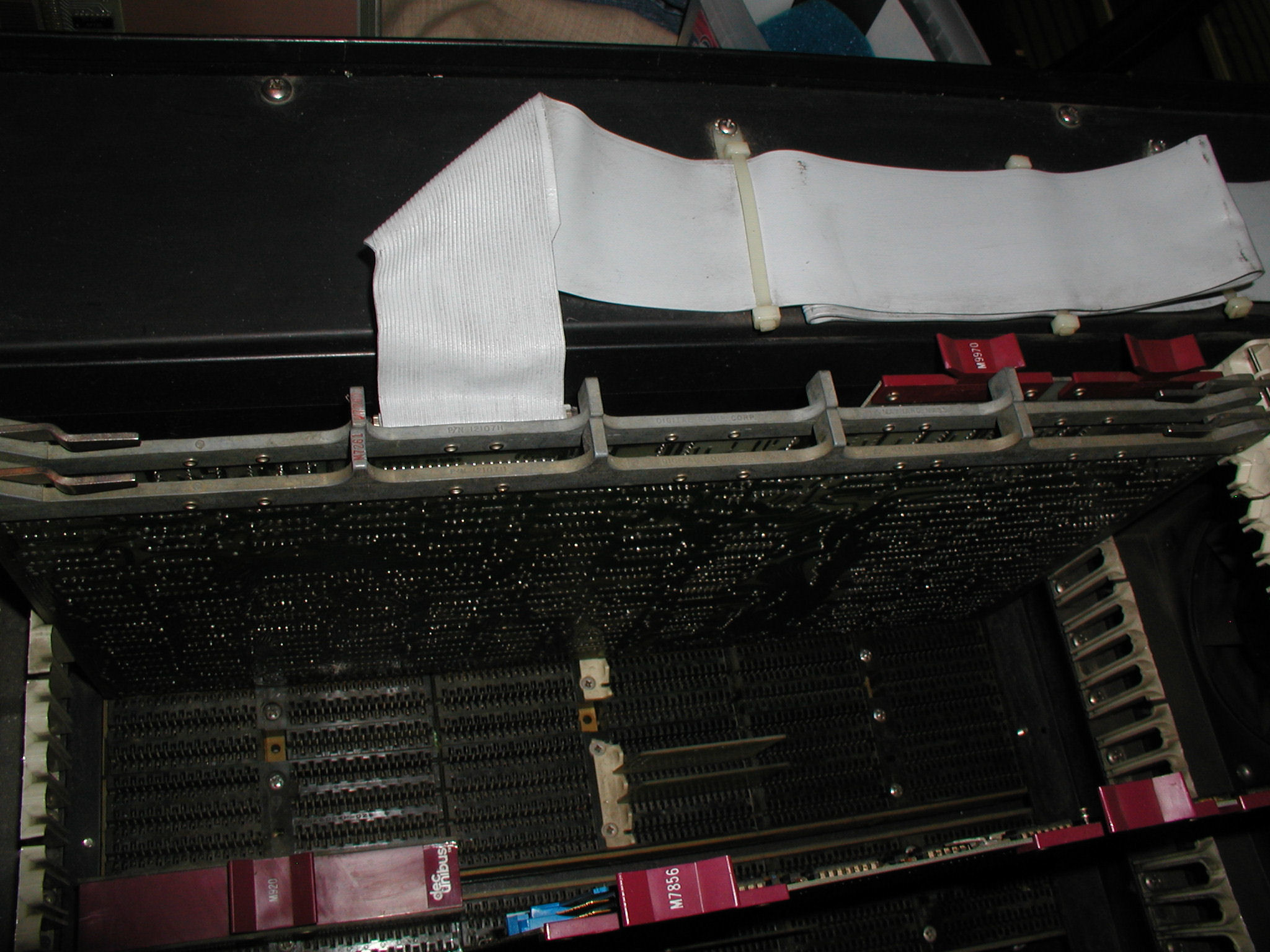
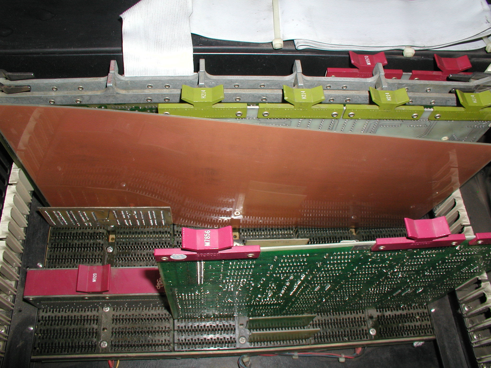
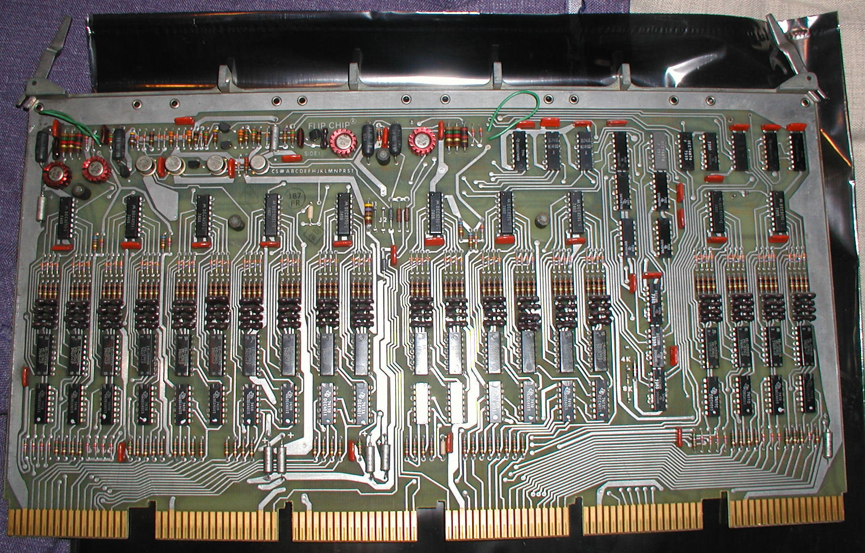
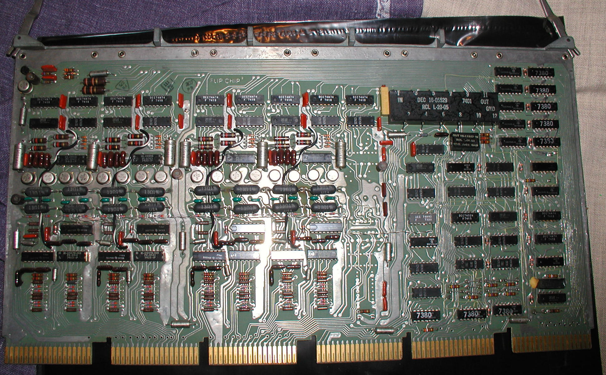
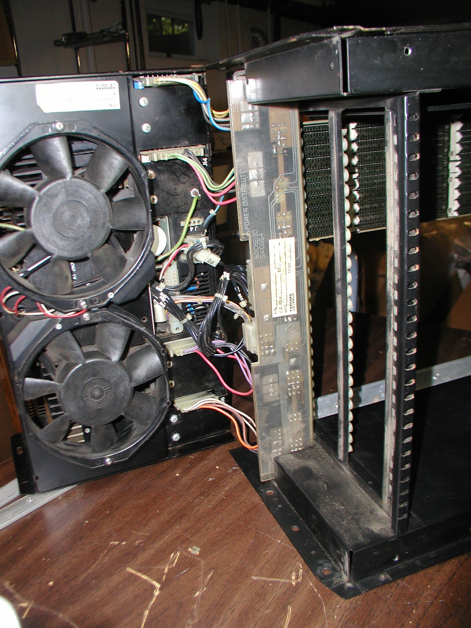
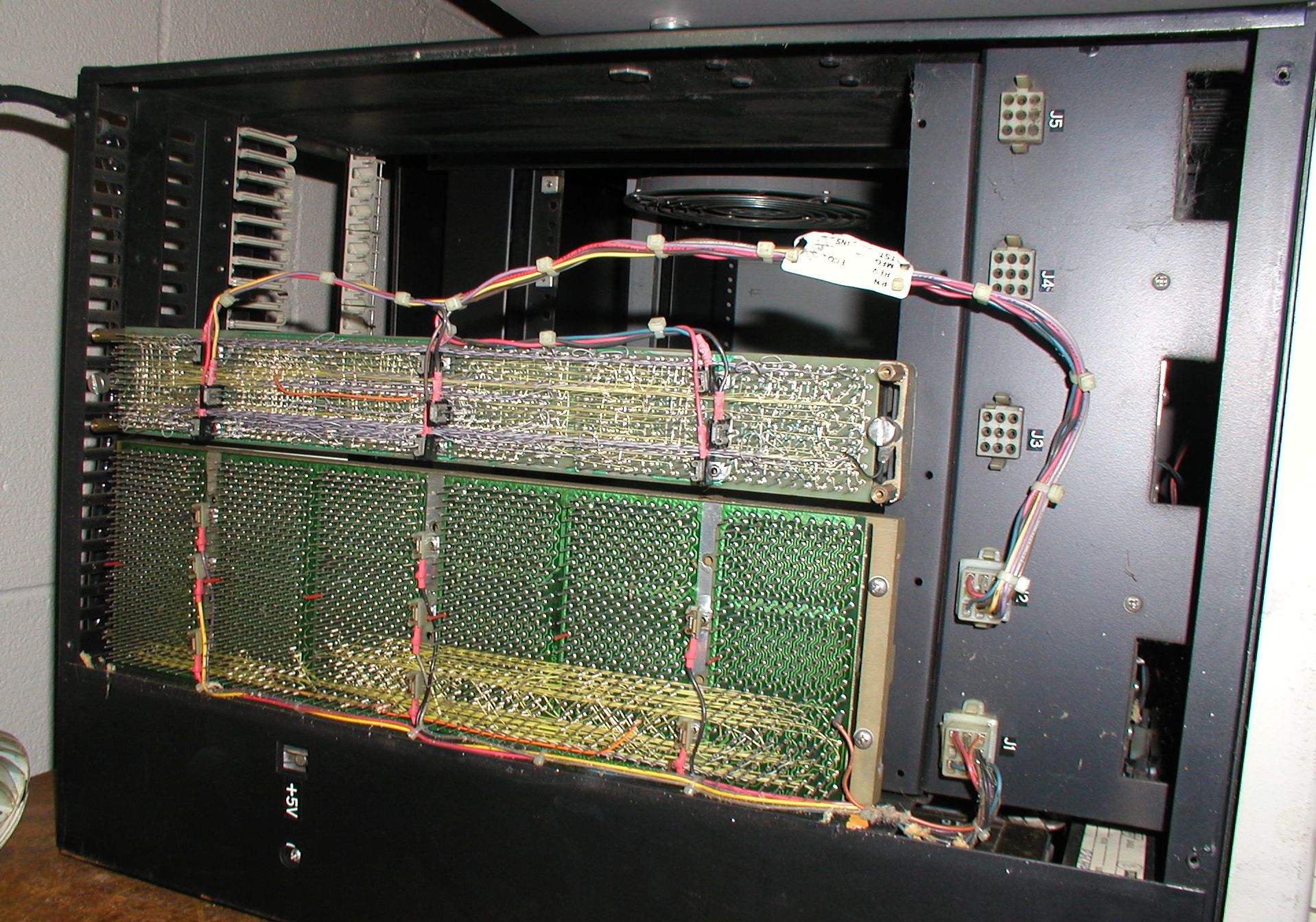 View of the pin side of the backplanes installed in the 11/05 NC. The bottom backplane is for the CPU/RAM. The top backplane is a DD11-B, used for peripheral devices that have Non Processor (DMA) Grant continuity such as the M7800 serial card. Click image for larger view.
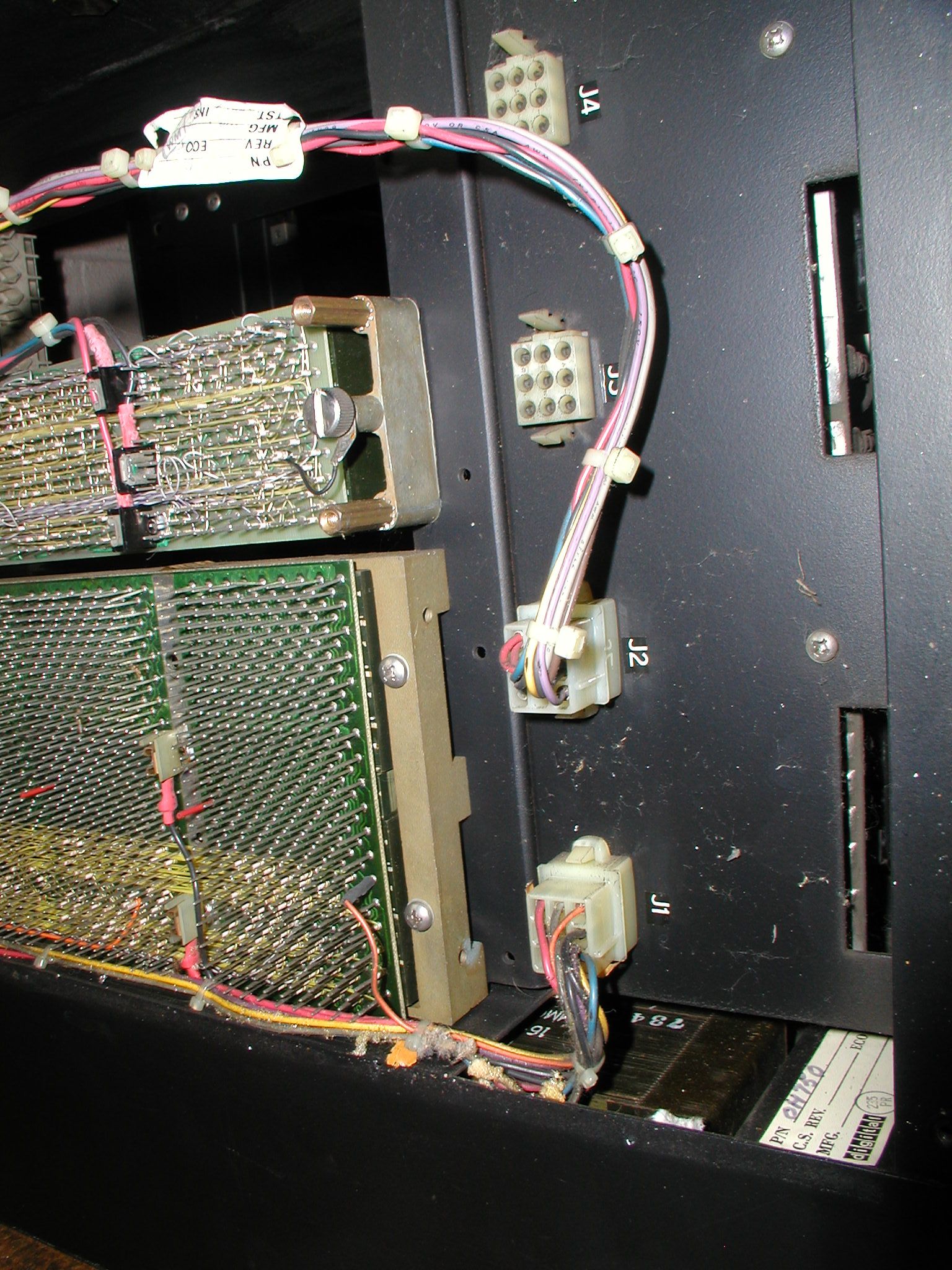 View of the backplane 9-pin power connector ports. Click image for larger view.
I was hoping that I might be able to run an RK05 drive from this box, but the power connectors are not compatible (although it may be possible to use an adapter). I don't have direct photos of the PDP 11/05 S power connectors, but I believe this model chassis is RK05-compatible. Here is a photo that shows the back side of the power connector board of the PDP 11/05 S, note there appear to the 6 and 15-pin connector ports. Reply |
|
Resources:

Popular Topics and FAQs
Past Issues:
Before we switched over to a blog format, past page archives here:
Vintage Computer Festival East 3.0 June 2006
Commodore B Series Prototypes July 2006
VOLSCAN - The first desktop computer with a GUI? Oct 2006
ROBOTS! - Will Robots Take Over? Nov 2006
Magnavox Mystery - a Computer, or? Jan 2007
The 1973 Williams Paddle Ball Arcade Computer Game Feb 2007
The Sperry UNIVAC 1219 Military Computer May 2007
VCF East 2007 - PET 30th Anniversary June/July 2007
The Electronic Brain August 2007
Community Memory and The People's Computer Company October 2007
Charles Babbage's Calculating Machine December 2007
Vintage Computing - A 1983 Perspective February 2008
Laptops and Portables May 2008
From Giant Brains to Hobby Computers - 1957 to 1977 August 2008
Historic Computer Magazines November 2008
World's Smallest Electronic Brain - Simon (1950) December 2008 - Feb 2009
Free Program Listings Spring 2009
Computer Music Summer 2009
Popular Electronics Jan/Feb 1975 - Altair 8800 Fall 2009
Early Microcomputer Mass Storage Summer 2010
3500 front 1
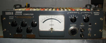
This image was selected at random from the archive. Click image for more photos and files from this set.