
Jump to Teletype Photos
"..it's difficult to imagine that even one of you has never seen the media, or doesn't know how paper tape operates..." - Kilobaud Magazine July 1977
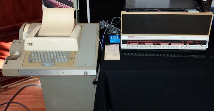
The Teletype Corporation teletypewriter was the most popular mass storage and general I/O device for early microcomputer users from 1975 to early 1979.

It's slow, It's noisy!
As often described in magazines like Kilobaud and Byte the teletypewriter was slow and noisy but it was also easy to use. Early micro manufacturers built their computers with teletypes in mind as evidenced by the fact that they had serial port circuitry that could by default interact with the Teletype's 20 milliamp current loop. Futher, manufacturers had not yet started making printers and displays for home use.
The Teletype was actually 4 devices in one - a keyboard for console input, a printer for console display, a line printer, and a tape reader for input and papertape punch for output. This is what made these so useful - they also served as an I/O station and printer. It was the perfect all-in-one device for early micro users. IBM Punchcards very popular for minicomputers but not micros, cassettes were not yet prevalent and disk drives and hard drives too expensive.

The Teletype Model ASR 33 could be purchased for less than $1000 for a refurbished unit and $1300 new with everything.
Storage Specifications
Papertape Storage Benefits
Teletype Model ASR 33
ASR 33 Tape Specifications
ASR 33 Communications Specs
ASR 33 Data Specifications
Alternatives to ASR 33
ASCII Teletype Format Revealed
Motorola Papertape
The lines of a motorola papertape start with either S0 - leader/beginning of code to be read (not shown in image above), S1 - data, or S9 (end record).Here is an example of the end of a paper tape code segment (Motorola format). You can tell because the last line always has an S9 at the end of it:
S1131C102C20DEBD19217E167DBD185FD6259626A3
S1131C209B27C900D70297037E167DBD1999DE282C
S1131C30DF2C9C022742D6029603902DD22C2A1C1C
S1131C40D62C962DBD015ADF2CD6029603BD015A1F
S1131C509C2C2724A600BD02270820F4D602960354
S1131C60BD015ADF2ED62C962DBD015A9C2E270875
S1131C70A600BD02270820F47E167DDEDBDF027E8F
S1071C80167D0000C9
S9030000FC
Here is how to understand the data. Let's take one of the lines:
S1131C70A600BD02270820F47E167DDEDBDF027E8F
The "S1" at the beginning means "this is a line of data"
1. The two-character byte count - how many 8-bit bytes there are to be expected in this line, in two char hex format INCLUDING the checksum = 13 (Hex)
2. 1C70 refers to the starting address in HEX of this line of code. Each two-character instruction represents a memory location. (i.e. 1C70 contains the instruction A6, 1C71 contains 00, ... etc.)
3. Count with your fingers to locate BD, this instruction is indended for memory location 1C72.
4. The two 7E's (embedded within the line) refer to the code in memory locations 1C79 and 1C7F respectively
5. The byte count is located in the 3rd and 4th position of each line. Full data lines' byte counts are 13 HEX (= 19 in decimal notation). If you count all the pairs of numbers starting after the S113 (count the four-character memory location and the 15 two-character instructions) there are 19 pairs = 13 HEX pairs of instructions. INCLUDING THE CHECKSUM. [i.e. 1C70A600BD02270820F47E167DDEDBDF027E8F = 19 pairs decimal, 13 hex) Note how the final data line starting with S107 is shorter, thus less of a two-character byte count.
6. The last two characters of every line is the checksum value, which is the one's complement of all 8 bit bytes ignoring carries. In this case 8F. The checksum is not part of the program code.

Example of Motorola format papertape records
Break down of an S1 line (refer to image above):
S1 = "this is a line of data". "S plus number" indicates record type.
13 = "this is the two-character byte count - how many 8-bit bytes there are to be expected in this line, in two char hex format INCLUDING the checksum"
00CB = the starting address in hex
2E 2A 4B etc. is the data (2 char hex values)
NOTE: The checksum at the end of each line is the one's compliment of the sum of all 8-bit bytes dropping call carries including the byte count, m address, and data. If the checksum is non-zero, an error is thrown by the monitor.
S9 - end of information indicator, stop the loader program and often used to indicate where to jump to in order to execute the program (not pictured in image, see code snippet above).
Intel Papertape
Same basic principle as Motorola, different order. Intel papertape format uses a colon as the start character (:), followed by a two character byte count, then the four-chracter address, a two-character record type, followed by the two-character data pairs, and ending with a two-character chusum.:10C8A000FFFFFFFFFFFFFFFFFFFFFFFFFFFFFFFF00 (a line of data starting at address C8A0. Record type = 00 (data), followed by a string of FF instructions, ending with a checksum of 00.
Picking out your ASR 33
These are some of the things to take into consideration when selecting a teletype. Note that the ASR 33 is the model most often used to interface with a microcomputer, but other models can be used as well. Photos of teletypes hereIs it complete?
Is there rust?
Does it look like it was opened (to scrounge for parts)?
Did an animal make a nest inside?
Are the fuses present/blown?
Are all of the keys aligned correctly?
Print head ok?
What do you need to restore a teletype?
1. Basic toolkit, solderkit, wire stripper, electric tape, needle-nose plyers2. Electricity measurement apparatus of choice
3. Various colored wire, 8 alligator chips, and/or a 4 or 6-wire cord that you can splice. Best Colors: green, white, black, red.
4. spade lugs - "the things that attach to the antenna screws at the end of a RF adapter" - you'll find these useful
5. EIA connect kit of choice if the computer you're attaching the teletype to has a 9-pin or 25-pin port. The little pins that often come in these kits are useful for testing.
6. 7/16 OD - 5/16 ID vinyl tubing (6 inches or more)
7. Cleaning supplies of choice - q-tips, paper towels, soap/water, canned air.
8. Extension cord
9. Notebook / camera to take picture before disassembly.
10. MANUALS and SCHEMATICS!
11. Refer to the manual for proper lubrication points and cleaning procedures. Ask an expert for your particular model.
Where do I get parts?
Replacing Rubber Print Head Pad
DO NOT test your teletype until you have replaced the print head pad. Old print head pads will have turned to mush by now, but that's OK!1. First remove printer ribbon, but note how it was attached so you can return it into the proper position.
2. Cut out the pad leaving only the hammer's metal striker bar. Replace with a 7/8 inch long piece of 7/16 OD - 5/16 ID vinyl tubing like a sheath over the ba.r see photo here. Look between the two ribbon spindles for a clear-plastic pvc tube cut and placed over the print hammer.
3. Every time you replace a printer ribbon, check the tubing. You may need to replace the tube after a lot of use.
Use caution when opening your ASR 33
There are three screws behind the metal "Teletype" strip in the front. You have to first remove the LINE/OFF/LOCAL knob then slide the strip down. Here is a picture of the three screws, view with the cover removed and the knob re-attached.
There is often but not always one tiny screw that holds the cover on the left side by the papertape reader. You can see the little hole in this picture
There are three knobbed screws in the back. (Pic after cover removed)
Remove the printer paper advance knob
Carefully remove cover, avoid the papertape reader lock.
AVOID removing the keyboard cover unless you have to! - Very hard to put back correctly! That said, with care you can put all of the thin metal bars back the way they were, if you take a picture before you start, or refer to photos of working units. A crossed bar anywhere - keyboard, punch, or reader can cause the system to short circuit and not print correctly.
How to Check the Communications Settings
Most of the time you want to set your TTY for 20mA current loop and full duplex.1. The large, green, flat resistor on the TTY base near the call control unit (a flat 4-post resistor with a blue wire on post #4)
2. Set purple wire to contact 9 of the terminal strip
3. Set brown-yellow wire on terminal strip post 5
4. white-blue wire on terminal strip post post 5 also Terminal input to the teletype to contact 6 for negative line and 7 for the positive line. (printer punch) Terminal output (keyboard - reader) contacts 3 and 4 (not polarity sensitive)
There are Two Ways to Connect to Your Computer
1. Plug In connectors (molex)2. Terminal Strip
If you're making a cable with a special connector to match your particular computer card EITHER the terminal strip or #2 connector can be used. If you have something attached to both at the same time you'll get crazy results. Of course your computer must have the ability to generate a 20 mA current loop, the computer generates the current, NOT the teletype. You can use a 20mA to RS232 converter to overcome this problem, how-to is not covered here, but contact me for info on this subject.
What are Plug in Connectors?

There are 8 molex-type connectors behind the call control unit (near the three fuses). The top left is #1, bottom right is #8.
#2 connects to the computer.
For each of the eight connectors, pin hole one is located at bottom right, see numbering array below, the important holes are in bold:
15-14-13
12-11-10
09-08-07
06-05-04
03-02-01
#2 connects to the computer.
For each of the eight connectors, pin hole one is located at bottom right, see numbering array below, the important holes are in bold:
15-14-13
12-11-10
09-08-07
06-05-04
03-02-01
How to connect to the computer via the number two connector:
Picture above shows location of #2 connector (marked with red "2" and arrow).Transmitted data return (-) attaches "number 2 connector" #7
Received data return (-) attaches to num 2 connector #5
Transmitted data send (+): #2 connector 8
Received data send (+): #2 connector #6.
Wiring the Terminal Strip

Terminal Strip is located behind the plug in connectors of the UCC-6
How to connect to the computer via the terminal strip:
You can bypass the #2 molex connector by attaching the 4 wires from the computer directly to the terminal strip instead. The terminal strip is located behind/below the connectors. If you remove the 8 plugs from the plug-in connectors and the terminal strip fiber cover, you'll reach the terminal strip of an ASR 33. The four posts of the terminal strip you need: 3,4,6,7. Note the numbers printed above their respective terminal's screw post. These four wires travel through the reader control and eventually out to the computer.Transmitted data return (-) attaches to terminal strip screw 6
Received data return (-) attaches to terminal strip screw 3
Transmitted data send (+): Terminal Strip 7
Received data send (+): Term strip 4
And then it was over...
1975-1979 was the proverbial "Indian Summer" for the teletype, an unexpeted life extension for a long-in-the-tooth machine whose prominence in the 1950's and 60's was slowly fading by the mid 1970's. The adoption of the teletype by microcomputer users was short-lived. The appearance of superior and less-expensive alternatives as the 1980's approached finally ended the reign of the teletype and Teletype Coporation announced that they would discontniue manufacture of the Model 28, 32, 33, 35, DRPE, BRPE and 4210 by the end of 1981. The end of an era.
Sources located in Documents Section of this web site.
Image Title: CGRS FRONT PANEL SYSTEM
 This image was selected at random from the archive. Click image for more photos and files from this set.
This image was selected at random from the archive. Click image for more photos and files from this set.Resources:
Popular Topics and FAQs
Past Issues:
Before we switched over to a blog format, past page archives here:
Vintage Computer Festival East 3.0 June 2006
Commodore B Series Prototypes July 2006
VOLSCAN - The first desktop computer with a GUI? Oct 2006
ROBOTS! - Will Robots Take Over? Nov 2006
Magnavox Mystery - a Computer, or? Jan 2007
The 1973 Williams Paddle Ball Arcade Computer Game Feb 2007
The Sperry UNIVAC 1219 Military Computer May 2007
VCF East 2007 - PET 30th Anniversary June/July 2007
The Electronic Brain August 2007
Community Memory and The People's Computer Company October 2007
Charles Babbage's Calculating Machine December 2007
Vintage Computing - A 1983 Perspective February 2008
Laptops and Portables May 2008
From Giant Brains to Hobby Computers - 1957 to 1977 August 2008
Historic Computer Magazines November 2008
World's Smallest Electronic Brain - Simon (1950) December 2008 - Feb 2009
Free Program Listings Spring 2009
Computer Music Summer 2009
Popular Electronics Jan/Feb 1975 - Altair 8800 Fall 2009
Early Microcomputer Mass Storage Summer 2010