PDP 11/40 Power Supply Issue!
SHARE |
|
 PDP 11/40 Power Supply Issue!
 |
by Bill Degnan - 08/12/2008 22:02 |
|
Nooo! The console and power supply light flicked out while in use.
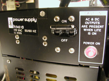
WTD: Power Supply or Power Supply Module. The part number on the front is "H742a" and it's the big part of the power supply in the back. In front (looking from the side) are power modules. The modules and the console power are attached to the "H742a" Other H74x supplies should work. Here is the wording on the unit: Dec Power Supply H742a Caution AC & DC OUTPUTS ARE PRESENT WHEN LIGHT IS ON POWER ON (( )) ------------ where (( )) = the light bulb. The supply's red indicator light no longer comes on, nor do the console lights, though the fans still run. In the meantime I will test with a volt meter and so on, maybe there's a bad connection. More to follow. Reply |
|
 PDP Power supply
 |
by Michael Corder - 09/25/2008 02:47 |
|
I used to repair the DEC supplies for our systems (one was a '11/35 I think). If I remember, most of the problems were the output transistors, and if one went, they all did (Along with a bit of circuit board trace). It was long ago, but I'll try to stir up some memories. They weren't 'real' sophisticated. I would get out the ohmmeter and start checking the power semis. I think the actual regulator was like a ua723 IC or something (I have those ICs). Those things also had a brutal overvoltage crowbar circuit if I remember, (Protected the computer at the expense of the supply). Now I'm thinking that played a part.... I also remember some were a pain to get apart :-).
Reply |
|
 PDP 11/40 Power Restoration
 |
by Bill Degnan - 11/04/2011 18:04 |
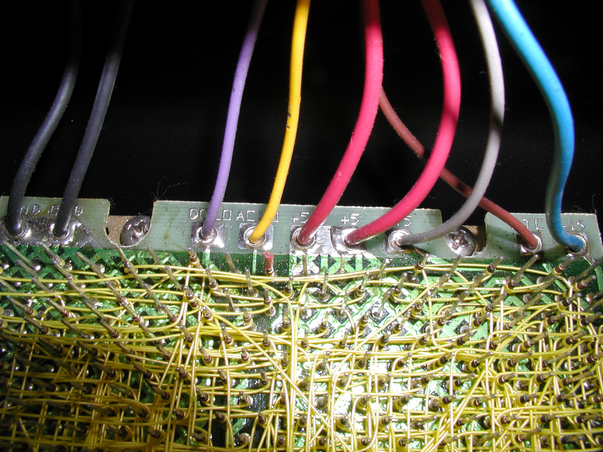 View of the PDP 11/40 wirewrap backplane where the DC power inputs are located. At present no 5V+ is detected, but the +15V and -15V do have power. The lights on the front panel are not activated. Click image for larger view.
 When the switch is moved into the on position, all fans come on, and the light shines to indicate that AC and DC outputs are present. I checked the fuse inside of the h742a, and it was OK.
 I removed and probed SU1 and SU2 to learn that no +5V being fed into the backplane. The 5V lines are the 2 red wires from both SU1 and SU2. Click image for larger view. View of power connectors
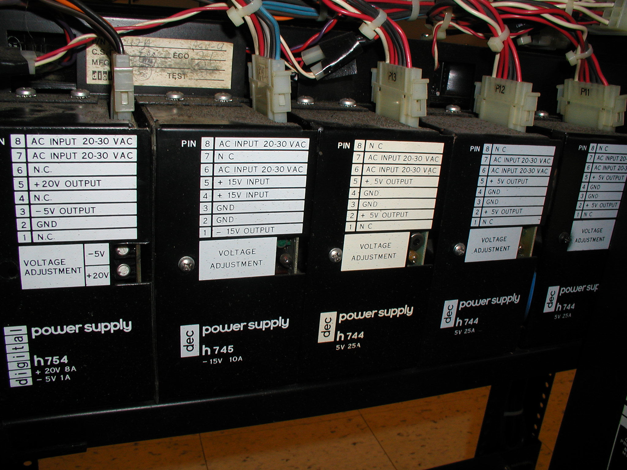
The h742a feeds the DC power supplies: h754 (+20V 8A / -5V 1A) h745 (-15V 10A) h744 (+5V 25A) three of these. NEXT - is one or more h744 bad? More power supply pics (date = 11/6/2010) http://bitsavers.org/pdf...0/1140_SystemManual.pdf http://www.miim.com/faq/...ware/unibfaq.html#h744w http://bitsavers.org/pdf...P00311_BA11-K_Oct74.pdf Reply |
|
|
Diagnosing H742 15V Problems |
by Bill Degnan - 03/04/2012 22:13 |
|
The backplane is not getting -15 or +15V, and the PROC and BUS lights are lit on the front panel. No interaction with the front panel is possible.
The 5V seems OK, so I turned my attention to the H742 itself and the H745 voltage regulator in slot D of the voltage regulator bay. There's a melted 25V cap on the regulator. I tried a replacement H742 from a PDP 11/05 with a good cap, but I don't know if it's a good one otherwise. I checked the H742 itself. It was dusty but the fuse was good and the fan was spinning. I need to check the output from this unit and repair if necessary. I read up about how the H742 power supply works. Not sure yet what's wrong, but I am probably in the ball park to think to suspect the H742 15V output, and to assume the H745 was either damaged as a result of over voltage, or it's OK (with the repaired cap). Reply |
|
|
DEC H742a Power Supply |
by Bill Degnan - 10/12/2012 20:54 |
|
Did not find anything wrong with the H744 H745, H744. I have a few spares. I have returned to the H742a, to check the power supply control board, responsible for 15+V
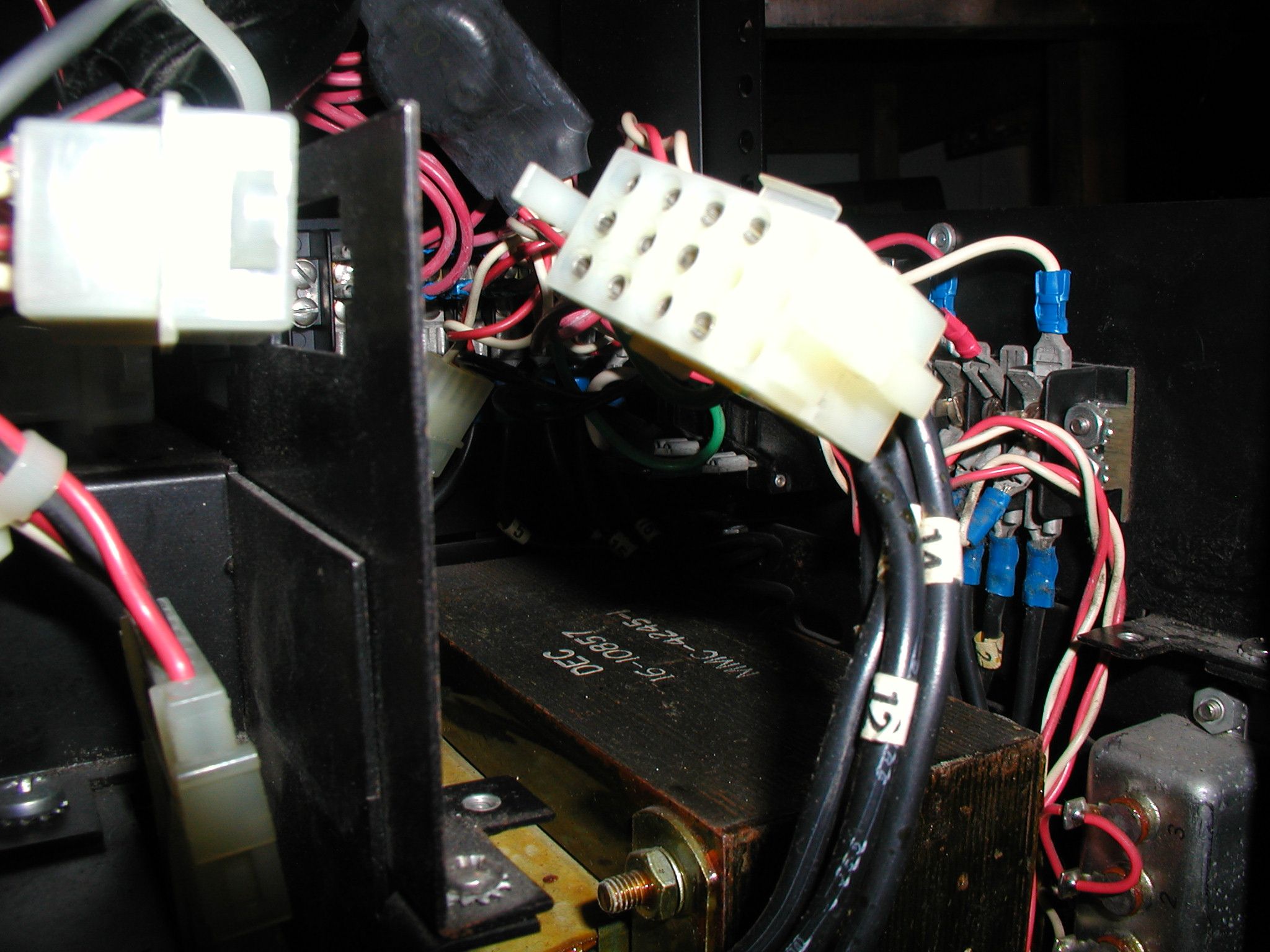
Took pics of the inside components so I can see under high magnification for obvious issues. Dirty but intact. Manual for parts is here http://bitsavers.trailin...rawings_Rev_P_Jun74.pdf h742a pic 1 h742a pic 2 Reply |
|
|
Replaced 5Amp Fuse |
by Bill Degnan - 04/14/2014 14:47 |
|
Replaced Fuse. That brought back all the marginal power values from the regulators. One of the 744's is too high, needs to be brought under 5.1V per spec (it's 5.2ish). DC Low reading off the backplane of 3.6v and an AC low of 1.8v....is this bad? I think AC Low is too low, according to the manual it should be closer to the DC Low.
PROC and BUS lights on the front panel but no interaction with switches possible. Thanks Malcolm for helping me lift the power supply out of the rack, and for locating the bad fuse. Reply |
|
|
Voltage Testing - AC Low Logic Fault? |
by Bill Degnan - 04/19/2014 16:18 |
|
regulators' output from front to back:
h744 - both +5v = 5.00 h744 - both +5v = 5.00 h744 - both +5v = 5.00 h745 - -15v = 15.06 (note this regulator has a +15 input = 16.1v ) h754 = -5v = -5.06 +20v = 20.09 Backplane readings -15v = -15.06 LTC = 2.29 +15v = 16.10 (input TO regulators) +5v = 4.76 * +5v = 4.76 * ACLO = 1.727v DCLO = 3.46v * Something in the backplane (a card I assume) is bringing down the +5v? What causes the ACLO to be 1.727v? I read that it should be closer to DCLO. The front panel BUS and PROC lights are on, front panel is unresponsive (still can't read/write to memory, halt/run, etc.) Thoughts 1. I read a web page that said another 11/40 owner pulled the connector from the power distribution board to the CPU backplane (assuming it doesn't have any power on that connector) and re-applied power. Doing so allowed him to interact (although incorrect results) with the front panel. 2. Do I have an open grant chain? The next three are from "Hints on Testing a Dead PDP 11 site http://www.psych.usyd.edu.au/pdp-11/hints.html 3. check backplane with oscilloscoe for a ripple, and make sure it's less than 200mV on the +5 supply. 4. "..If you find low voltages at the backplane, but normal at the regulators, check the connectors, especially the MateLock types used on the modular regulators .." 5. check the AC and DC low signals. These are bussed via the Unibus (and Q-Bus), and a failure in any system box can shutdown other parts of the system (depending on the supply design). Again, use an oscilloscope to check for pulses (it should normally be above 2.5 volts) since it may be putting the CPU into power fail mode. All the DC voltages may be OK, but a fault in the AC low logic can still stop the CPU from running. Fault in ACLO causing +5V to pull low? I need more documentation. Reply |
|
|
H742 Power Connector P9 Readings |
by Bill Degnan - 03/08/2015 23:34 |
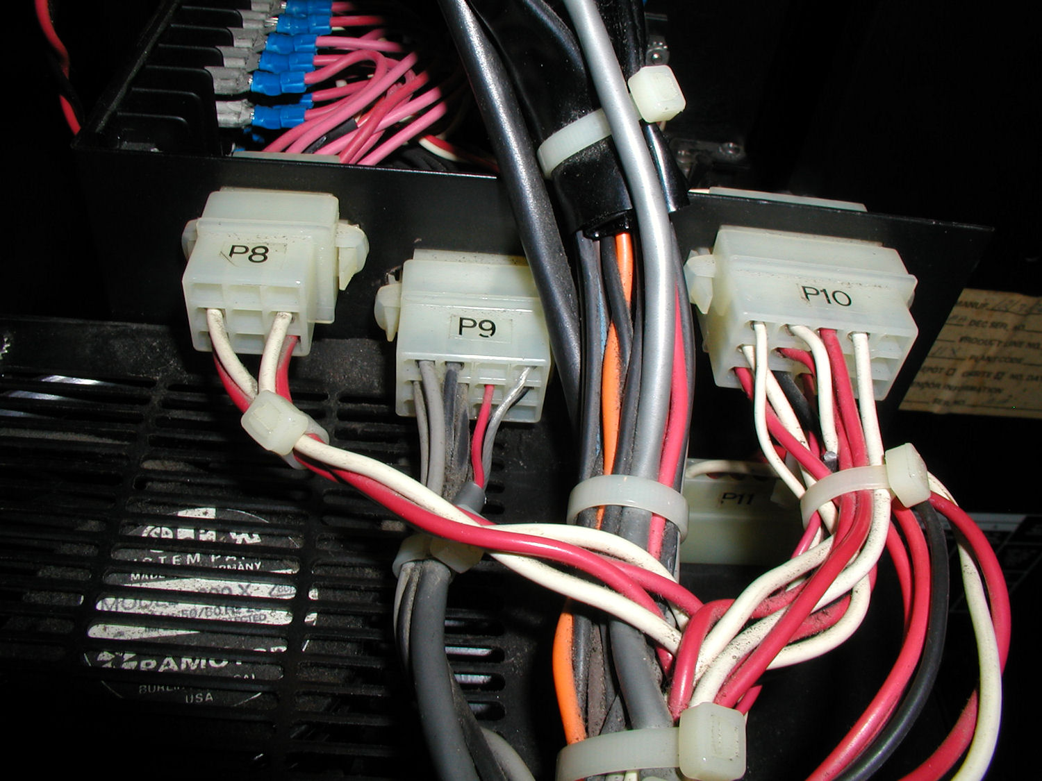 Power connector P9 outputs DC voltages. Click image for larger view.
Measurements from power connector P9 pin 1 - 9.47V pin 2 - +16v pin 3 - +16v pin 4 through 7 GND pin 8 AC LO 4.8v (actual 3.53v) pin 9 DC LO 4.8v (actual 3.53v) pin 10 AC LO 4.8v (actual 3.53) pin 11 line clk pin 12 DC LO 4.8v (actual 3.53) Note the system actually uses AC LO from pin 8, and DC LO from pin 12. 8 is in the middle of the third column, 12 is at the top of the 4th column. P9: 3 6 9 12 2 5 8 11 1 4 7 10 conclusion #1 - repair the H742 Power Control Board. AC LO and DC LOW should be closer to +4.8v 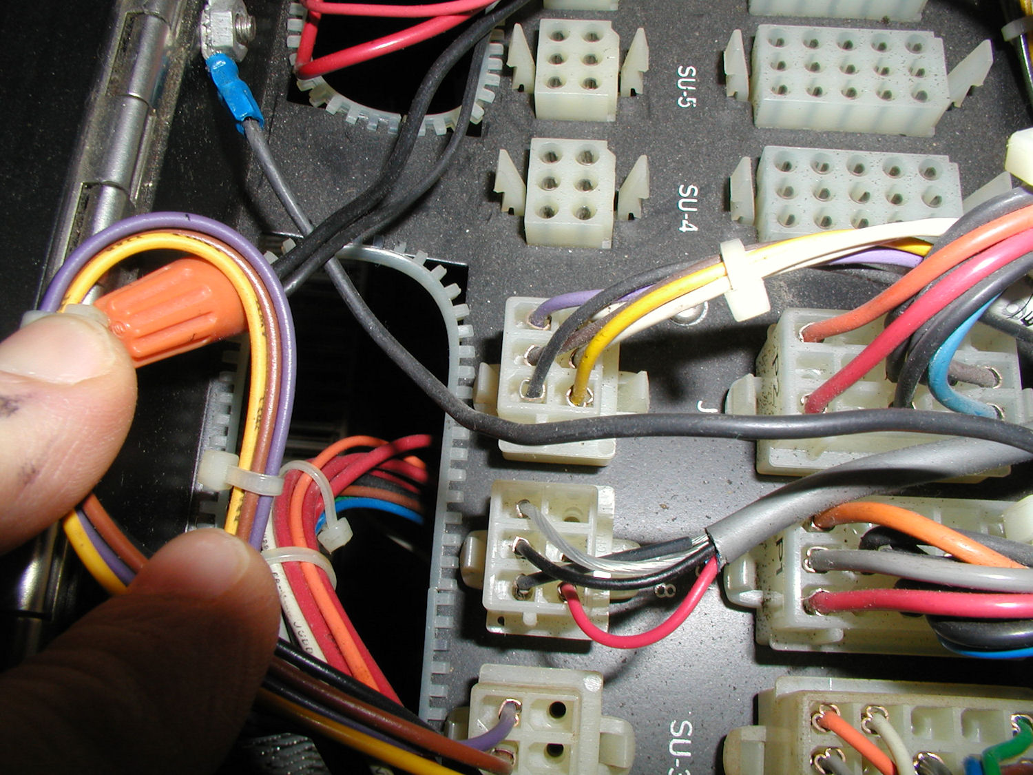 Next I checked voltages at J18, where DC LO and AC LO are fed to the backplane. Click image for larger view.
The AC LO line goes from pin 8 of the P9 connector to the top right pin on J18. The DC LO line goes from power connector P9 pin 12 to the bottom left most pin. J18: - - - AC DC - - GND Readings: AC LO - 1.72 (should be 4.8) DC LO - 3.52 (should be 4.8) Conclusion #2, something is pulling AC LO down further, in addition to a fault in the H742 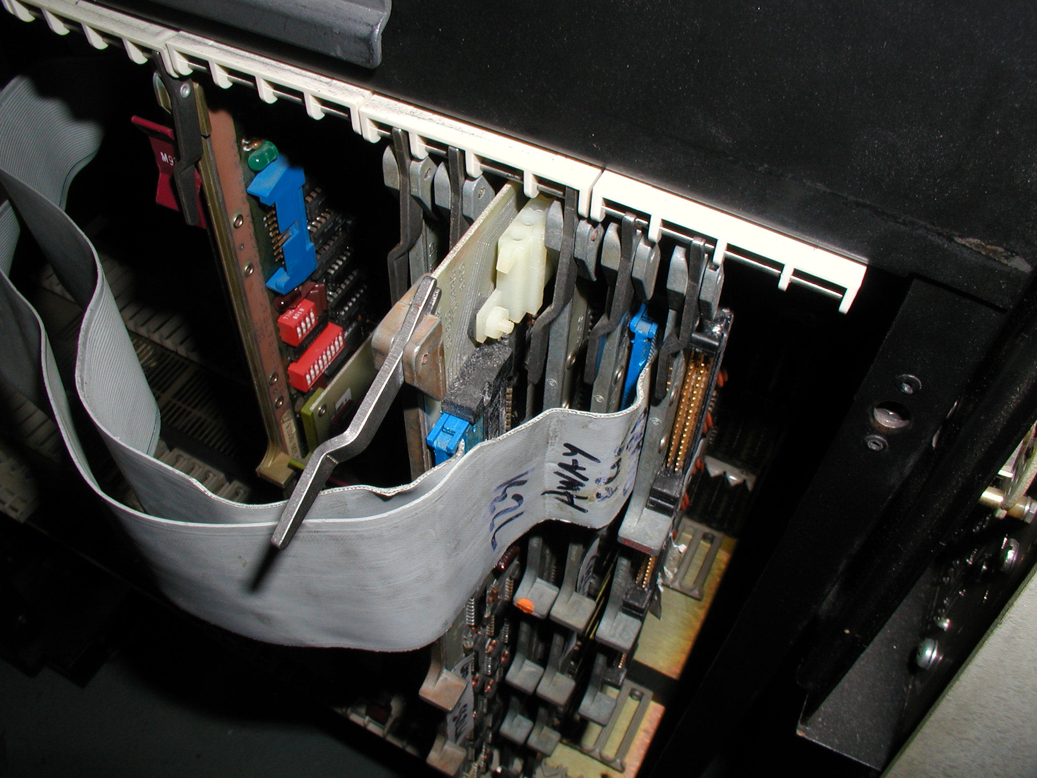 I pulled the STATUS card, M7235 from the backplane because it has the DC LO and AC LO signals. Click image for larger view.
With the M7235 removed, the voltage on J18 pin 8, the AC LO, returned to 3.52. Conclusion #3, there is a possible fault on the M7235 card pulling AC LO down further. But because the reading is exactly half with the card installed I think this is by design, not a fault. Checking the manuals... http://bitsavers.trailin...1/1140/KD11-A_Maint.pdf NEXT: remove and service the h742a power control board. I was told on a DEC user group list to suspect the caps on the AC LO line. Reply |
|
|
742a Power Control Board Repairs |
by Bill Degnan - 03/13/2015 11:00 |
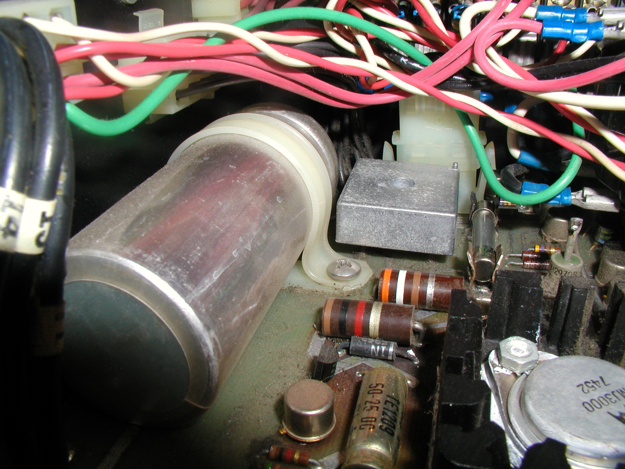
 View of the blown 20uF 60v cap in C3 of the power control board. This cap has since been replaced. This cap is in the AC LO circuit and is likely a major cause of the issues reported in this thread. Click image for larger view.
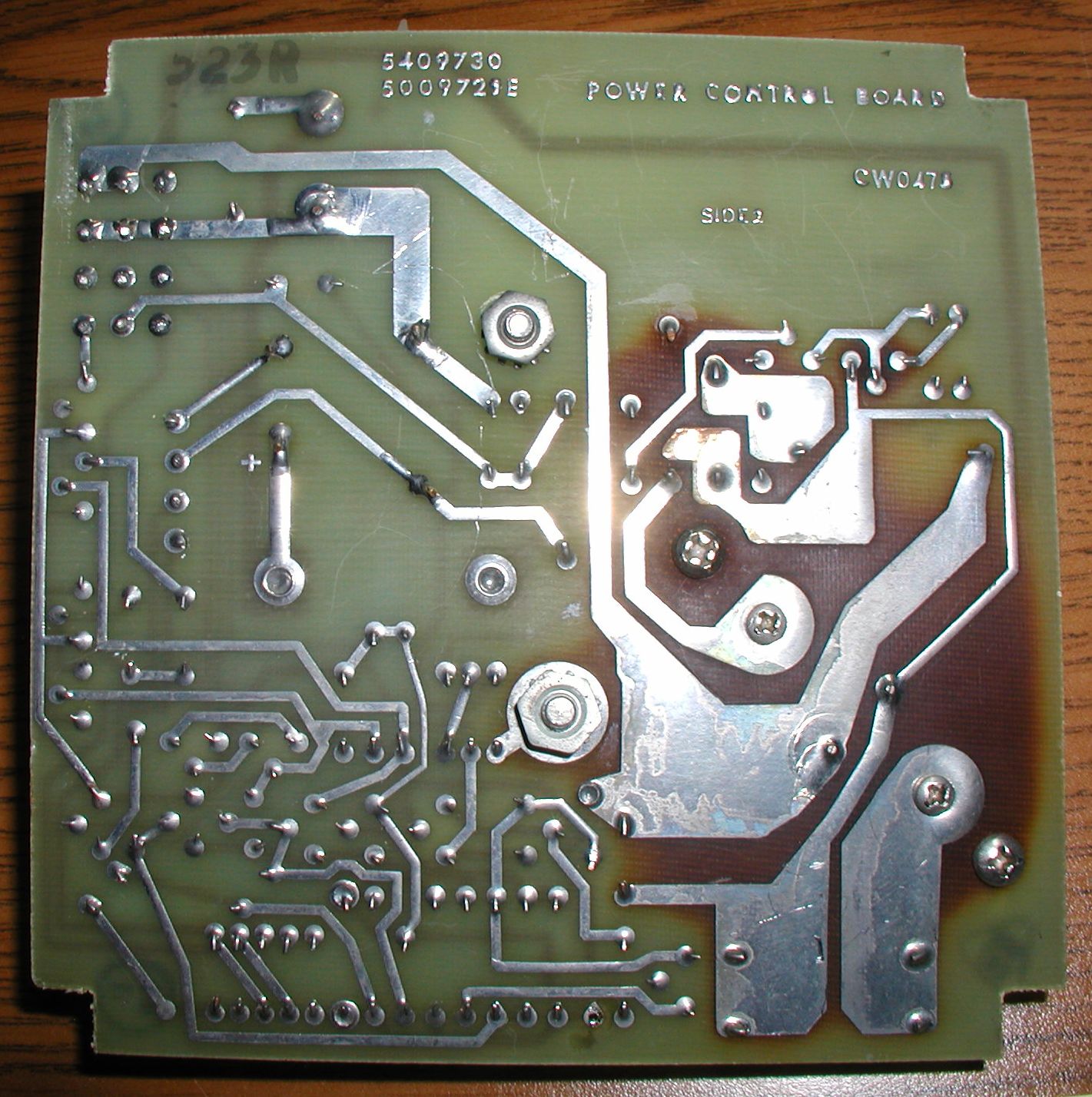
It was not easy to remove the power control board from the 742a. Here is a picture of the power supply with the board removed and the cables disconnected. The secret is to remove completely only two screws (corners behind C1 and the large regulator), and only to loosen the two hard to reach screws (one is near the indicator light, one is infront of C1). The screws do not actually go through holes in the board, they simply hold the board in place in the corners. 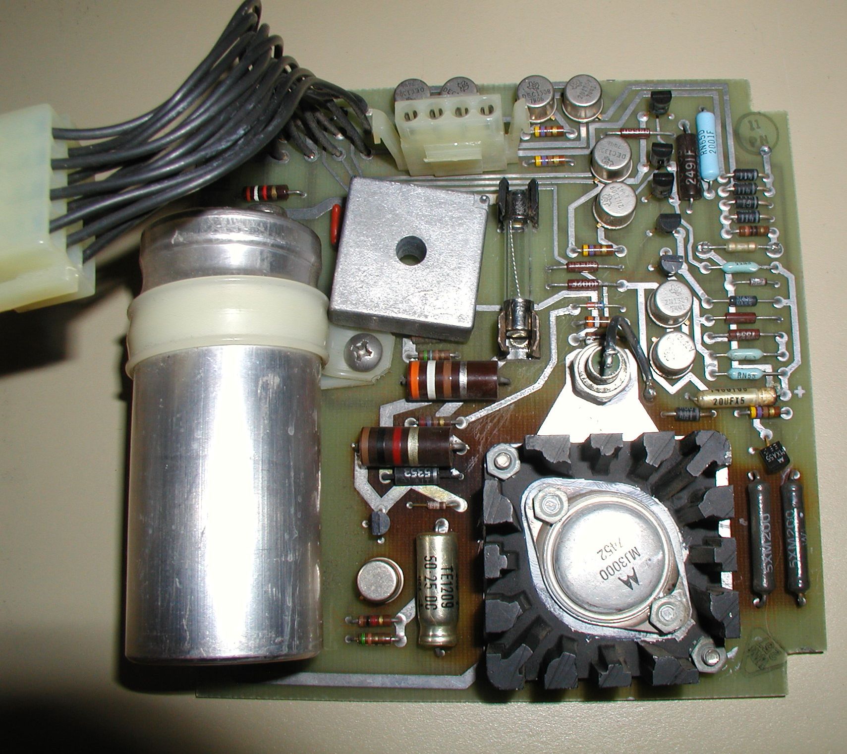 Here is a view of the top of the board. Click image for larger view.
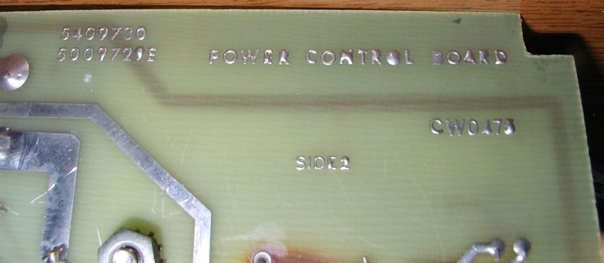
742a power control board Underside Picture of the part numbers printed on the bottom of the board. You'll notice that the board is stained brown from head (?), similar to what you'd see in a teletype UCC-6 power control board. I don't think that this is a problem, just evidence of hot resistors. Because it's tough to remove the board, I am going to also replace the following caps: C1 - 5.8KuF 40v large cap with screw posts on top (measured marginal) C2 - 50uF 25V I also put in a 5 amp fuse in the fuse holder (large fuse pictured above). I forgot I had a 3 amp fuse installed temporarily. The 3 amp still held enough for testing but why take chances.... The other small 1/4 amp fuse within the row of diodes seemed ok. Reply |
|
|
Restore Complete |
by Bill Degnan - 03/16/2015 12:24 |
|
Replacing the 20uF 60v cap in C3 fixed the AC LO issue. I will still replace the other caps, but I can now EXAMINE memory. I will run a more thorough set of testing, and create a new log to describe adding a RL02 disk drive and terminal.
Reply |
|
|
Not so fast...DC LO again |
by Bill Degnan - 06/07/2015 22:11 |
|
After about an hour the fuse blew out and we have DC LO again. I have resumed the repairs, this time to be more thorough.
Reply |
|
|
Digital 742a Power Control Board Repair |
by Bill Degnan - 06/28/2015 12:19 |
|
Started things off my making an easy-to-read printable PDF of the parts list and schematic. Download
Next I will use to trace the DC LO and AC LO circuits to locate the bad ICs and replace them. Reply |
|
|
742a Repairs |
by Bill Degnan - 07/12/2015 10:57 |

I printed out a nice large schematic to follow. Hosted a vintage computing hacking workshop, with help from Kyle O. he helped me debug the h742a power board. The problems with the board were resolved as far as we can tell, every part was checked caps and a transistor or two was replaced. We did a lot of schematic vs. actual measurements of the power board out of circuit, and also installed but not plugged in to the rest of the system. Still AC LO... hmmm...We set up a sort of a test harness to make it easier to probe important electric junctions, A few hours later, finding nothing else to fix or replace we started removing cards. When we removed the M7856 serial board and bootstrap terminator the DC LO AC LO problems vanished. Now able to test RAM, save, run simple front panel programs. I re-inserted the M7856 and bootstrap terminator, system was still OK. The assumption is that one of these two cards was not installed correctly. Continued here Reply |
|
|
Basic stress testing |
by Bill Degnan - 07/17/2015 10:51 |
|
Running system for a few hours to measure power output over time while running "chase the lights"
Here is what I have so far, almost made it one round of counting RAM 32K DC LO 4.65 (in spec of 4.8 +-.2v) AC LO 4.69 (in spec of 4.8 +-.2v) 5V+ 5.00 15v+ 15.88 15V- -15.08 These are basically good, the DC and AC LO are typically lower than 5V because the values represent the gain variance of the transistors (I believe). Reply |
|
Resources:

Popular Topics and FAQs
Past Issues:
Before we switched over to a blog format, past page archives here:
Vintage Computer Festival East 3.0 June 2006
Commodore B Series Prototypes July 2006
VOLSCAN - The first desktop computer with a GUI? Oct 2006
ROBOTS! - Will Robots Take Over? Nov 2006
Magnavox Mystery - a Computer, or? Jan 2007
The 1973 Williams Paddle Ball Arcade Computer Game Feb 2007
The Sperry UNIVAC 1219 Military Computer May 2007
VCF East 2007 - PET 30th Anniversary June/July 2007
The Electronic Brain August 2007
Community Memory and The People's Computer Company October 2007
Charles Babbage's Calculating Machine December 2007
Vintage Computing - A 1983 Perspective February 2008
Laptops and Portables May 2008
From Giant Brains to Hobby Computers - 1957 to 1977 August 2008
Historic Computer Magazines November 2008
World's Smallest Electronic Brain - Simon (1950) December 2008 - Feb 2009
Free Program Listings Spring 2009
Computer Music Summer 2009
Popular Electronics Jan/Feb 1975 - Altair 8800 Fall 2009
Early Microcomputer Mass Storage Summer 2010
O2 Running Doom
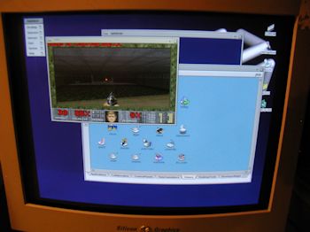
This image was selected at random from the archive. Click image for more photos and files from this set.