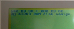
 During a cold startup, having no RAM disk initialized, the machine reports
the amount of RAM and prompts for the amount to be reserved for the RAM disk.
The Epson PX-16 is a machine with a multitude of configuration and expansion options. Lacking any source but the machine itself, this overview might not be complete.
 During a cold startup, having no RAM disk initialized, the machine reports
the amount of RAM and prompts for the amount to be reserved for the RAM disk.
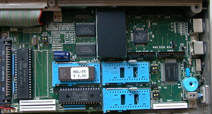
A machine with the disk unit connected, defines this RAM disk as D:. The memory consists of some fixed memory (256 kByte) and up to three "RAM disk" banks (384 kByte each) as removable modules. One module placed makes 640 kByte RAM. It is the black rectangle above the blue ROM sockets. All these are static CMOS RAMs. The RAM disk uses zero or more 32 kByte blocks of this RAM.
 Five ROMS can be placed in the PX-16. One is a bootable MS-DOS 3.20,
480 kByte large (512 kByte minus the 32kByte BIOS), three others are in
ZIF sockets beneath the keyboard.
The fifth is a mystery, but it is reported by the ROMID command. It
could be connected to the CN7 connector, at the left. All
these ROMS have a drive number. The MS-DOS is E:, the MEL-PX ROM is F:,
G:, H: and I: are empty.
The MEL-PX ROM comes with the memory card interface which is a PCMCIA forerunner, as it has a smaller connector (8 bits, PCMCIA is 16 bits). This specific interface accepts only Mitshubishu MEL cards. Other 8 bits memory cards like the Texas Instruments MC1128K160-20 are recognised, but cannot be formatted by the MEL software. The MEL-PX rom contains CONFIG.SYS, MEL-PX.SYS, MELFORM.EXE and MELFORME.EXE. The *.SYS files are loaded on startup, defining the card interface as drive J:. The *.EXE files are a German and English formatter program.
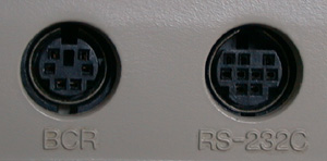
 The PX-16 features a serial port
with a wierd 9-pin mini-DIN connector, but standard otherwise. The BCR
is supported by the E:BARCODE.COM.
Barcode interfaces were very popular in those days.
Epson PX-16 Serial port
 9  8   7        1 Rx         Retro-engineering with
                 2 CTS        SYSTEST.EXE.
6  5  4  3       3 DSR        Great tool!
                 4 DCD
   2  1          5 RI
                 6 Tx
                 7 RTS
                 8 DTR
                 9 GND
Epson PX-16 Barcode port
  6   5         1 - BTXD;  UART transmit data    2 - BCR; BCR read signal
4      3        3 - CG;    Case ground           4 - GND; Logic ground
   2 1          5 - LOGIC; BCR +5V power supply  6 - LED; BCR LED control power supply, or BCR status signal
Other interfaces are parallel printer and floppy drive, both with non-standard connectors and a color graphics monitor connector. A switch allows you to switch from LCD to CRT. The whole LCD screen module is detachable.
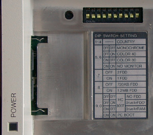
 Lots of configuration options
found under the card reader cartridge (top right).
Most notable are the "HC BOOT" options, booting from the internal
MS-DOS ROM.
Latest update: 2011-11-12