System Expansion Bob Couger W6KPS Do you all too often get an OM (out of memory) error? Are you tired of waiting for a pro- gram to load or to get a few dozen data files into memory? On the other hand, maybe your Level II, 16K system is now very, very reliable and you are afraid of the problems associated with the Radio Shack expansion in- terface. There is another way. AlternativeLNW Research offers a circuit board and a manual for $69.95. It claims to have all of the features of the Radio Shack expansion chassis and then some. Also mentioned is software compati- bility. They further claim a “quiet bus” design that elimi- nates some of the memory prob- lems. After receiving additional data from LNW, I carefully com- pared their specs with those of Radio Shack. It appeared that LNW’s board would do every- thing that Radio Shack’s does, plus the serial interface was not an accessory that connects via- |
a poor connector, as is the Radio Shack version. The board had heavy power buses and lots of bypass capacitors.
I ordered the kit last spring and received it only 30 hours later. I spent some time compar-ing LNW’s circuitry with that of Radio Shack. Anyone building the LNW board should purchase the expansion interface hard-ware from Radio Shack. The manual has a good parts list. Actually, the parts are listed in several ways. The system al-lows partial construction for those who don’t need all the fea-tures. For instance, if you only want additional memory, and don’t need a floppy disk, the manual explicitly tells you what parts to buy. On the other hand, parts are sorted alphanumeri-cally to make it easy to order and inventory. The hardest item to find was the cable. Radio Shack wanted $25 (love/hate... hate this time). One supplier had both ribbon connectors with one end termi-nated, and also40-pin soldertail connectors, so out with the sol-dering iron! This is the part of the job I really hated. I detest symmetrical conneators that can be wired and plugged in up-side down. These dumb un-keyed connectors are the worst design feature of all. Anyway, all the parts finally, |
were found from three suppliers, not including Radio Shack. Many of the parts (such as bridge rectifiers, SCRs) were called out as Radio Shack “276-” type part numbers.
AssemblyAt a local parts store I found a 16" x 13" x 3" chassis. I wanted lots of space for a good power supply, a modem, and an inter-face for my ham radio. While having these mounted on a sin-gle chassis makes a neater as-sembly, my real objective was to keep radio interference to a minimum. Regarding power supplies, the manual suggests buying an-other Radio Shack module simi-lar to the one that powers the |
keyboard. Check at your local Radio Shack to see if they have a bad one laying around. Chances are they do and will sell it to you for less than $5.00. You can go home, pry it apart and replace the fuse. A sche-matic is included in the con-struction manual. I bought separate tranform-ers and mounted them internally with a power line filter that hope-fully keeps voltage spikes out of the logic. Shown in Fig. 1, the power supply will run four ex-pansion interfaces. First I mounted the board, the power transformers, and cut the slots for the ribbon connectors. Next I assembled the board per the guidelines of the manual. I used sockets for all chips. The |
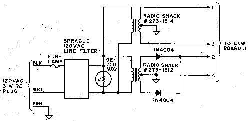
Fig. 1. This circuit will take the place of the Radio Shack power sup-ply. The power line filter generate transients of sufficient magnitude to activate the crowbar circuits if the GE-750 is not installed. Even larger transformers may be purchased if you anticipate using floppy disks and a common supply. |
232 - 80 Microcomputing, February 1981
pins on the sockets were ta- pered so that they barely ex- -tended through the board. This made inspection of soldering hard, but I managed by going slower than I normally would. There was nothing else tricky or unusual about assembling the board. Power UpWhile the manual directs you to plug in the chips prior to pre- liminary power checks, certain jumpers are not installed. With these removed, no power is ap- plied to the chips. Follow the di- rections exactly. This section performs voltage checks to find errors or bad parts that could cause damage. When power was first applied to my unit, both fuses blew. This was caused by the crowbar cir- cuit, which is designed to short the power supply to ground if the regulator fails. Testing de- termined that turn-on transients generated by the line filter were to blame. The problem was corrected by installation of a metal oxide varistor (MOV), General Electric Part No. GE-750. This compo- nent draws almost no currerit at 120 V ac but at higher voltages the resistance decreases dra- matically so that spikes are shorted out. The MOV totally coriects the problem. The short probably would not have hap- pened if I had used the Radio Shack power supply, but a MOV is good to use across the ac line of any sensitive equipment. After this was fixed, all power supply voltages checked. I in- stalled the jumpers, powered up the chassis, and rechecked the power supply voltages. I then re- moved power and connected to my keyboard. You should hold the BREAK key when powering up a System that has an expansion chassis with no disk drives. If you don’t, you will have a screen full of gar- bage. To recover, hold, BREAK and hit RESET. I did this and the system came up with the MEM- ORY SIZE? prompt the way it normally does. I hit ENTER and after what seemed seconds the system jumped to BASIC in a normal manner. I learned later that this time delay is normal, |
since the TRS-80 has ROM resi-dent routines that automatically check and .size the memory. With the additional 32K, it takes longest. I then eritered PRINT MEM and the computer returned 48340, the correct value for a 48K machine. The next thing I tried was to PEEK and POKE in-to the new memory locations. Attempts to POKE or PEEK above 32767 (top of memory for a 16K machine) returned an OV erior (overflow error). Chasing the Wild.GooseWhile I thought it interesting that the system recognized the new memory, the fact that I couldn’t PEEK or POKE into it convinced me that there was a hardware problem. Out came the old oscilloscope. I pulled aut all the chips except those to support the new memory. One came out; socket and all; I had completely missed soldering it to the board. While this would not have caused my problem, I pulled the board and carefully inspected for missing parts and integrity of soldering. Finding no further problems, I then pow-ered up and continued trouble-shooting. After hours of exten-sive testing, I tried loading some machine language programs in-to the new memory. .Radio Shack’s RENUM con-tains modules for 16, 32 and 48K machines. When I tried the 32 and 48K versions, they loaded and worked. I then loaded T-BUG and found I could wiite and read to high memory ad-dresses with no problem. RSM has a memory test option, and this ran faultlessly. I began to suspect cockpit errors. After more troubleshooting, I got out my TRS-80 owner’s manual, and found that to POKE and PEEK above 32767, you have to sub-tract 32767 from the desired memory address. Thus to POKE X into 32768, you POKE(32767 – 32768),X or POKE – 1,X. I tried it, and of course it worked. System Expansion PortThere are two 40.-pin edge connectors on the LNW board; Either one can be connected to the TRS-80. The other is avail-able for devices that work direct- |
233 - 80 Microcomputing, February 1981
ly off the expansion port, such as a page printer. The bus termi-nation resistors are installed near one of these connectors. The manual suggests that these resistors may not be necessary if you are using a device on the expansion connector that has its own termination networks. l. installed the termination resis-tors and have experienced no problems. Real Time ClockThe real-time clock is only of limited use without a disk oper-ating system. Various programs such as the one on page 21 of Radio Shack’s Expansion Inter-face Hardware Manual can be used to test the clock. The pro-gram seemed to work well but the clock gained about three minutes in ten hours. Using my frequency counter, I checked the frequency of the internal 4 MHz xtal. oscillator. and found it running high. By trial and error, I found that increasing the value of C15 from 27 to 39 pF put the oscillator |
right on frequency and made the clock accurate. The exact value varies with the tolerance of the crystal. If the frequency is high, the value of C15 should be in-creased, if low, vice-versa. Ac-tually this whole effort is unnec-essary since the clock loses time anyway during disk read and write operations. The clock has proven useful in disk opera-tion for timing program events in BASIC programs. Dual Cassette OperationCassette operation is slow, but dual cassettes open up a new world for data handling if |
you are interested in editing data files. The LNW board has the decoder and relay driver. All that is required in addition is an external relay which I mounted iri'my chassis. The system de-faults to cassette recorder two when powered up; that is, if you power up and command CLOAD or CSAVE the system will ac-tivate cassette two. However, if system tapes are loaded, the relay will energize and load it from recorder one. When you. have this feature enabled, you should specify CLOAD #-1 or CLOAD t-1, 'A' etc. However, if you just say CLOAD or CSAVE |
'A', etc. the system will energize the last recorder selected from previous cassette operations. Serial PortThe serial port uses a com-mon chip called a UART (univer-sal asynchronous receiver/transmitter). This chip is almost a magic device. You inject paral-lel data, and out comes serial data, or input parallel data and out comes serial data. The chip can do both jobs simultaneous-ly even with unrelated data of different baud rates. Of course, it takes a clock or two and a few jumpers, but I call it magic be-cause of a design job I did years ago using 15 chips or so to do the job that one chip does now. Actually I like this. serial port so well that I wish the LNW board had two of them. It would be nice since it is possible that one might want one port for a line printer and one for a modem. LNW includes this fea-ture,that Radio Shack charges over $100 for. You have to pur- |
234 - 80 Microcomputing, February 1981
hase the additional parts, but the cost is less than $15. Line Printer PortThe line printer port, like every other LNW feature, works like Radio Shack’s and is designed to work with a parallel printer, ’ using the Centronics interface. For those using a serial printer, the serial interface can drive it; With no modifications to the printer or the LNW board, you can set up the serial interface .for the right baud rate and punch in a software routine that will link the LLISTs and LPRINTs to the serial interface. The driver software program is included in the. manual. A better way is to follow the .instructions of Chapter 6 which route signals that would normal- ly go out .the normal parallel printer port through the serial port. This allows use of the LPRINT and LLIST commands without any special software. A switch is provided to allow the serial interface to be configured back to work with something |
like a modem.
A still better approach would be to build a separate parallel to serial converter which would plug into the printer port and convert to the type of serial level (usually RS-232) required by the printer. While either of the above techniques work well, I wanted to leave the serial port alone for . a modem in the future. I con-structed a small wirewrap card that is mounted inside and de-rives power from my Heath H-14 line printer. Since it plugs into the normal printer port, LLISTs and LPRINTs work the same as they do using a Radio Shack or Centronics printer. Those of you who are handy with a wirewrap tool can receive a schematic of what I am using by sending me five dollars. The schematic also has optional cir-cuitry to operate a Heath H-14 directly off the expansion port of an unmodified 16K Level II ma-chine. The DiskI had my LNW chassis up and |
running for almost a month be-fore my Pertec drive arrived. Dur-ing this time I ran every test I could to ensure that it was work-ing. The Pertec box was ripped open and the four-drive cable quickly connected to the drive. Without pausing to read any di-rections, I plugged it into power and to the chassis interface. I then inserted the TRSDOS 2.3 system disk that I had pur-chased and turned everything on. The drive came on, the screen went blank, and up came DOS READY. RF InterferenceYou may not care about this if you are not a radio amateur or shortwave listener. The TRS-80 generates a lot of energy in the radio frequency spectrum. It seems to be the worst in the 40 meter region. Someday I am go-ing to hook my antenna tuner up to it and I probably will be able to talk to. Japan if I can figure out some way to key it. It seems that every accessory |
added causes the noise level to come up. I built my LNW board in a large metal box with the in-tent of building in my M80 (ham radio interface). This would eliminate one cable as a radiat-ing source. The line filter also helps. I have done nothing to correct the radiation caused by the TRS-80 but I do not observe any increase in noise when the expansion interface is connect-ed or disconnected.
Software CompatibilityI have tried NEWDOS+, NEWDOS 80, Electric Pencil, Percom’s DOS, etc., etc. All run exactly as on a standard TRS-80. The LNW system does not expe-rience the mysterious system crashes that some of my friends occasionally have. The LNW board performs. It is ”totally hardware and software compatible with Radio Shack products designed for the TRS-80. While the manual is good, the project is such that I would recommend it only for the advanced kit builder. |
235 - 80 Microcomputing, February 1981