Magnavox Mystery Binary Counter
SHARE |
|
 Magnavox Mystery Binary Counter
 |
by Bill Degnan - 01/11/2007 15:23 |
|
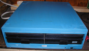
Please help me identify the use of this unit ... when was it built?
http://vintagecomputer.net/Magnavox/ Reply |
|
 Magnavox Mystery Computer
 |
by Greg Manuel - 01/12/2007 06:06 |
|
Hi Bill,
The site looks great. As far as I can make out on the lable, it looks like the following to me; Model Number : Reproduction Unit Finish: A - Wal (Walnut maybe?) Serial Number: 29 I hope this make4s sense and helps you. Have a great day, Greg Reply |
|
 Magnavox Mystery Computer
 |
by Bill Degnan - 01/12/2007 22:40 |
|
I spoke with a U of Delaware Computer Science professor today, Paul Amer, who suggested that this is a binary counter. It makes, sense, the reset button would start the counter over, the RCA jacks would be inputs/outputs. There are no computer logic circuits that I can detect.
Reply |
|
|
Magnavox Mystery Binary Counter |
by Lionel Theunissen - 01/17/2007 05:40 |
|
Hi Bill,
Almost certainly what you have there is an audio Reverberation Unit. That makes sense because of the RCA connectors on the back (audio in and out). Also that appears to be what the label reads to me. This was probably used in conjunction with an electronic organ or other electric musical instrument. The lights probably represent different taps on a delay line or the divider for the clock into a bucket-brigade delay which would determine the echo times which made up the "reverb". Lionel... Reply |
|
|
Magnavox Mystery Binary Counter |
by Bill Degnan - 01/17/2007 10:42 |
|
neat..I will try it out as a reverb!
Reply |
|
|
Magnavox Mystery Binary Counter |
by Bill Degnan - 01/25/2007 20:11 |
|
It's not a reverb unit.
Reply |
|
|
Magnavox Mystery Binary Counter |
by jesse laxson - 08/04/2007 14:58 |
|
Obviously pre-IC era. Factory PC boards. #48 pilot lamps. I would put an o-scope on those RCA plugs. Might suggest that since those are incandescent lamps, it won't be running REAL fast. Also, it was probably lashed together for in-house use. Might suggest that the scheme indicates that the bottom set of lights would indicate the input signal, while the top row would indicate the output signal...when the pulse train stops, you can decipher the lights to indicate how far behind the top row would be with the bottom row. Or vice-versa.
Reply |
|
|
Testing Homebrew Binary Counter |
by Bill Degnan - 10/06/2010 09:52 |
|
Hi Bill
It is not likely to be 5V logic. Most transistor logic use 0 and -10 or -12. You might first try just shorting the input leads. This is more likely. You might also try tracing out one flipflop and then measure the supply voltages. It seems there are two flops per board. I wish I could make sense of the written lable. I wonder what it was used for. Most counting applications would be in decimal. Dwight Reply |
|
Resources:

Popular Topics and FAQs
Past Issues:
Intel MDS 720 cleaned
This image was selected at random from the archive. Click image for more photos and files from this set.